Wood Carving Machine Software 51,Plan Wood Cuts 95,Cast Iron Quick Release Vise - Step 2
02.02.2021
Are you looking forward to DIY CNC router kit plans or coming up with an idea to buy affordable CNC routers for wood, aluminum, stone, foam, plastic with home use, small business, hobbyists, school education or industrial manufacturing? Check out the new CNC router machine buying guide for CNC router beginners, operators, machinists, wood fabricators, metal fabricators, foam fabricators, stone fabricators, woodworkers, metalworkers, and stoneworkers, we'll offer you best computer numerical controlled router machines with custom CNC routing service to fit your CNC projects, files, ideas, and plans.
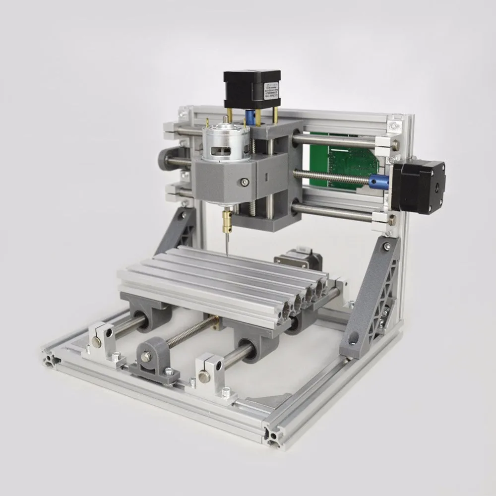
A CNC router machine is composed of CNC controller, CNC software, CNC operating system, frame, spindles, gantry, motor, driver, guide rail, ball screw, power supply, T-slot table or vacuum table, vacuum pump, collet, limit switch, rack and pinion. The most common CNC router tables by feet include 2x2 CNC router table kits, 2x3 CNC router table kits, 2x4 CNC router table kits, 4x4 CNC router table kits, 4x6 CNC router table kits, 4x8 CNC router table kits, 5x10 CNC router table kits and 6x12 CNC router table kits, the table sizes are also known as 16x16, 16x24, 24x24, 24x36, 24x48, 48x48, 48x96, 60x, 80x, and 80x in inches, someone may call the table sizes as , , , , , , , , , and in millimeter mm.
The X-axis is horizontal, the Y-axis vertical, and the Z-axis refers vertical to the other two axis. A computer controller reads G-code or other machine language instructions and drives a tool. In a 3 axis CNC machine, the tool is always vertical, and undercuts are not possible. In addition, a router machines can be equipped with a rotary axis 4th axis around the X, Y and Z axis, which is called as CNC router lathe machine.
It is mainly used for cylinder carving and cutting projects and some 3D CNC machining projects. Four axis are linked, which can work at the same time. The machine moves a tool on five different axis at the same time. The spindle can be rotated left and right with degrees around. These additional axis allow for shorter project time due to their capability of carving five edges of the material simultaneously.
The position of the machine is determined by a computer. The computer will tell the motors how much to move in each direction. The machine can be moved within that space. The machine is connected to a computer, the computer will tell it where to move.
First, the CNC operator should do the toolpath creation, the operator uses CAD or CAM software program to draw the shapes and create the tool path that the machine will follow. So, when you have some CNC machining plans, what kind of table sizes should be chosen?
CNC routers are widely applied in industrial manufacturing, small business, small shop, home business, home shop, school education, hobbyists and SMBs.
Soft Wood: Soft maple, pine, fir, hemlock, cedar, spruce, redwood. Plastic: ABS, PVC, PET, polyethylene, polycarbonate, polypropylene, polystyrene, cast and extruded acrylic, uhmw, phenolic, luan, vhmw, hdpe, mica, acetate, sintra, lucite, marine PVC, nylon, lexan, solid surface materials.
Stone: Tombstone, granite, natural marble, milestone, jade, artificial stone, bluestone, sandstone, ceramic tile. Metal: Copper, brass, bronze, aluminum, honeycomb aluminum, mild steel, stainless steel.
Foam: Sign foam, polyethylene, polyurethane, polystyrene, EVA, styramfoam, urethane, precision board, foam rubber, silicone rubber. Other Materials: PCB, ren board, fiberglass, vinyl coated panels, machinable wax, mat board, butter board, gypsum, magnetic rubber mats, composites, g10, leather, wood veneers, mother-of-pearl, delrin, rubber, modeling clay.
Different CNC router machine specifications have different costs, including machine bed, X, Y table T-slot table and vacuum table , spindle, gantry, ball screw, guide rail, vacuum pump, driver, motor, CNC controller, operating system, collet, rotary 4th axis, limit switch, power supply, rack and pinion. Machines from different brands have different service and support, which will lead to different costs.
Machines from different countries have different tax rates, different customs, different shipping costs. All of these factors will result in the final price.
If you want to buy a machine overseas, and get the final price, please contact us to get a free quotation, we'll calculate the final price of your required machines. Motor drive, the CNC machine kits equipped with low power motors are only suitable for routing double-color plates, building models, small signs, three-dimensional crafts and other materials.
This process has been popular for some time, but the power is too low, which greatly affects its application range. The machines equipped with high power motors are divided into two types: one type is a large format table, the format is generally more than one meter, but the accuracy of this type is generally poor.
The other type is a medium format table, this type is generally used for fine machining and organic sign making. Spindle motor, the spindle motor is also very important, because it is generally not covered by the warranty, and it needs to continuously work for a long time, so if the spindle motor has problems, which will affect the use of the machine.
Furthermore, it is the speed adjustable range of the spindle motor. The general speed adjustable range is thousands to 30, revolutions per minute. If the speed is not adjustable or the speed adjustable range is small, then the application range of the machine is limited, because different materials must be carved at different speeds. Machine bed manufacturing process: The high power machinery requires the body to be precise and stable when working.
Therefore, long-term high power machining should use the casting body to ensure its accuracy and stability. CNC controllers are also generally divided into two types: one type of controller is only driven, and all computing operations are completed by a computer. The computer is in a waiting state while the machine is working, and cannot perform typesetting work.
Another type of controller is controlled by a single board computer or a single-chip computer. This controller is actually a computer, so as long as the machine starts working, the computer can immediately perform other typesetting work, especially when working for a long time, the advantages are particularly obvious.
Ball screw and guide rails are also important parts. High quality ball screw and guide rails are the guarantee of machining precision and performance when the machine is used for a long time. CNC router machine has three control methods: ordinary variable frequency drive and control, vector control drive and control, and direct torque control. Ordinary frequency conversion is scalar drive and control, and its drive control characteristic is constant torque drive, and the output power is proportional to the speed.
The dynamic performance of ordinary frequency conversion control is not ideal, the control performance is not good at low speed, the output power is not stable enough, and it does not have the C-axis function. But the price is low, the structure is simple, and it is generally used for grinders and ordinary high-speed milling machines.
The vector control technology imitates the control of a DC motor, is oriented by the rotor magnetic field, and realizes the drive and control by the method of vector transformation, which has good dynamic performance.
The vector control drive has a large torque value at the beginning. In addition, the electric spindle itself has a simple structure and small inertia, so the starting acceleration is large, and the allowable limit speed can be reached instantaneously after starting.
This kind of drive includes open loop and closed loop. The latter can realize position and speed feedback, not only has better dynamic performance, but also can realize C-axis function. Direct torque control is another new type of high-performance AC speed control technology developed after vector control technology. Its control idea is novel, the system structure is simple and clear, and it is more suitable to drive and satisfy high-speed spindles.
Turn on the power of the control computer and monitor, and start the CNC software 2. Press the power switch. Turn on the spindle motor cooling water pump and check the cooling water flow. If the machine is turned on for the first time today, depress the handle of the lubricating oil injector once, and add lubricating oil to the lubricated part. Perform the mechanical origin return operation in the software, and eliminate possible collisions before the operation.
Manually move each feed axis 1 to 2 back and forth within the full stroke. Step 2, Workpiece Clamping. Place the cushion material in the center of the workbench. Place the workpiece to be processed on the mat. Use at least 4 sets of pressure plates to fix the workpiece on the worktable. Check whether the workpiece is clamped firmly. Find the edge and set the workpiece origin: 5. Move the spindle along the feed axis that accurately sets the origin until the tool will touch the workpiece.
Start the spindle. Switch to single-step movement with step size 0. Move in one step until the rotating tool touches the workpiece. At this time, a slight noise will be heard. Zero the workpiece coordinates of this axis or record the current machine coordinates.
Move the axis to move the tool away from the workpiece, and pay attention to confirm that the moving direction is correct. Disconnect the power of the routing machine to ensure that the spindle motor stops. Move the spindle to a position where it is easy to change the cutter, and place the soft material directly under the cutter to avoid damaging the cutting edge when the cutter falls. Fix the spindle with a small wrench, and turn the chuck nut clockwise viewed from top to bottom with a large wrench, taking care not to hit the cutting edge with the wrench.
Conventional Wood Carving Machine Software Video Milling. The perfect cutting is not too slow, not too fast, not too shallow and not too deep. Too many variables for a simple chart. The values below may be used in configuring milling operations when using a CAM program to generate G-code to make a cut, but unless your machine is essentially identical to the machine which they were used on, can be considered as only very general guidelines.
All values should be verified and tested on a scrap of material first, then one should adjust to match desired chip size and surface finish and time required for completion.
These tools are intended " In addition, one needs to decide upon a cutting depth advancement, and the amount of stepover how much each toolpath overlaps, see the Glossary. Interesting discussion of materials suitable for cutting on a Shapeoko and their characteristics in: Re: Material Advice.
Roughing passes, maybe up to 10 pounds depending on how aggressive you want to be. Edward Ford, the machine's designer has posted an aluminum milling video with the S3 with good finish and parameters that FSWizard spits out about 4 pounds for. CNC Speed Converter. The feed rate speed at which the machine head moves in XYZ space and the speed rate number of revolutions per minute the cutting tool revolves around its axis need to be proportional to each other, so as to have the machine cut out suitably sized chips.
The G-Wizard suggestion for plunge rate is to divide feed rate by of flutes. In contrast to the usual cutting formula, this simpler one has been suggested [35] :.
Chip load is a physical thing. It's the thickness of the thickest part of the chip that the cutter generates. If your cutting feeds are set up right i. That would be your chip load. I like to keep Wood Carving Machine Software Yoga chip load constant, since the thickness of the chip has a huge amount to do with where heat goes, where cutting forces go, and ultimately the cleanliness of your cut and the life of the tool.
I'll always start with the chip load to get a feed rate. Here's how that works:. You'll notice that cutter diameter doesn't come into play there. If you add it to your formula, you're going to come out with really weird numbers. Basically, I say I want each tooth of my cutter to take off a certain amount of material, say 0.
Now let's say my cutter has two flutes, so every time it rotates I have two chips being removed. In order to remove 0. Now I can multiply that out by my spindle RPM , because why not to get 0. You'll notice units cancel out to a sane unit of IPM for feed. That's just too fast! The thing is, it's not too fast. It's actually the appropriate speed to get a good cut.
I'm not vouching for 0. I'd actually suggest something more along the lines of 0. The thing at this point in time that will break your cutter is excessive cutting forces, which come from the last variable in our cutting equation: depth of cut.
Many places will have fundamental rules of thumb for how deep you should cut with your CNC router. Ignore that for these models.
I don't trust something that simple, as its bound to be overlooking something. In this case, proper chip and cutter loading. There are a lot of ways to use a lot of math to calculate how deep you should cut, but at the end of the day you're still using a shapeoko machine, which is quite flexible. What I'm saying is, every machine will be different and hard to predict.
Start shallow won't hurt anything and work down deeper and deeper until it sounds like your cutter is really loading down, then back off a shade and remember that value.
I usually suggest starting with 0. Those will be very light cuts, and you can play with increasing them more and more until you're happy with how the cut goes. One thing to understand is that depth axial depth, along the cutter vs width radial width, or stepover is very different in traditional machining as opposed to cnc routing.
In traditional machining, you tend to start out with a block of material slightly oversize of the actual part. You then whittle it away to reveal the part hidden inside, which usually involves very deep axial cuts with a very shallow radial cut. This is less than optimal, and means that we have to cut shallower to compensate. You can't choose an optimal depth and adjust the width to compensate as normal.
You can implement various strategies to do that when cutting parts out of a sheet or panel, but it really doesn't make any sense in that context because it's much less efficient from a cycle time perspective. Take the feeds and speeds for a small endmill in a particular steel alloy, then calculate the force needed to make that cut, a specific engagement. Then, calculate it out as a kinematics problem. The whole thing needs to be really stiff to cut steel.
If the deflection at the tip of the cutter cutter plus whatever it is attached to is more than the thickness of the chip, feed per tooth then it is guaranteed to chatter, and not cut well. Work hardening occurs when the chip of material being removed is thinner than that zone of material which the impact of the cutting forces affects. It is why steel and to a lesser degree certain non-ferrous alloys are so difficult to cut.
Many steels work-harden, especially austenitic stainless e. AISI , etc. Every cut involves large plastic shear deformation in a thin zone near the surface, and as a result, the freshly cut surface can be harder than the original material. Not optimal. Increasing cutting speed will increase temperature in the shear zone. In one way, that is beneficial because the strength of the material usually drops with temperature.
But: The hardness of the tool drops with temperature as well - edges will blunt quickly effect: rake down, edge radius up , tool life goes down more than productivity increases. Most of us have experienced this exact problem: Run a HSS drill at too high RPM in steel, and it will blunt before you make more than a little dent.
Note that different materials will respond to cutting in different ways, and will ultimately be cut with differing levels of accuracy. Please note that the values for a Shapeoko are copied into the page below at the appropriate points. Please verify on your machine with a test cut.
Carbide Create has two notable sets of feeds and speeds for the Shapeoko build uses a chipload-based calculation, while and later use a set of pre-calculated feeds and speeds which are intended to be quite conservative, so as to minimize problems. In Carbide Create build , feeds and speeds could be automatically calculated based on chipload.
This was discontinued in later builds. In Build , Carbide Create began using a series of tables for tooling and feeds and speeds. Formatted as CSV files, they may be readily modified and shared. Carbide Create.
A central tenet of this series is an acknowledgement that the hobby CNC routers need different numbers for different sorts of paths. Thus far he has done:. I made a test piece with 30, 6mm holes, using 2d pocket, bore and circular tool paths. All three strategies was tested with and without finish passes. With climb and conventional. And any combination. And I also tested boring conventional with 0. I haven't gone through the numbers thoroughly yet.
But so far a few things I've noticed. It seems Gadgetman was on to something with single-cut operations vs choosing a roughing and finishing two part strategy. All my best holes size, roundness and finish were made by single operations that did the full diameter at once!
Secondly using conventional milling produced the best results. Some with climb milling was ok as well, but the general result was that anything concerning climb milling be it complete single cut operations or used as finis passes gave a little worse result.
I had little luck with the any variation of the circular path, and it also does a very annoying z up movement with every completed Z level. The best two were simply 2D pockets normal pockets and bore cut as a single conventional milling operation. Those two produced the best looking holes and finish and was closest to spec. Of the two I think I prefer bore, since it's quicker to set up and quicker to cut. The ones I did as a rough bore with a finishing contour pass came out pretty bad, too small and with lots of chatter.
Ideally, all the Wood Carving Machine Software heat of a cut will be carried away by the chip — this is not always possible, so for some cuts in certain materials, coolant will be used. It may be applied in various ways, either through drip or mist systems see Upgrade Overview or one may fashion a dam or well in which to pour it.
Use a simple 3 x 3 matrix method to judge DOC and speed. Make 9 small square pocket s in a piece of the wood, and vary the speed and feed across the 9 also varying the DOC and feed. When a DOC and feed looks good, check to make sure the chips are little C shapes instead of dust or burnt dust. It is always a good idea to test and prove out a G-code path, esp. The industry-standard for this is machinable wax [50] , a combination of wax and a compatible plastic, usually polyethylene used in plastic bags and many food containers.
See below for feeds and speeds which are specific to this material, and other details, but it should be possible to use the G-code intended for the final material. Home Depot: Foamular by Dow Corning A given endmill, in a specific material will have a chipload suggested by the manufacturer.
Unfortunately, these don't directly apply to the less-rigid machines typically used by hobbyists. For aluminum: The most important thing is to make sure chipload is at least 0. RPMs are from users who have measured the speeds on their units [60] [61] , or extrapolated linearly. Ideally when milling metals one would use an upcut bit, so as to clear chips however, given the narrower bits which a Shapeoko is likely to be using, plunge depth is typically limited to 0.
Even so, some users have found it helpful to increase the width of cuts to aid in chip clearance as noted in Re: ORD Bot Hadron. Forum discussion full of suggestions: Re: Aluminum. One consideration when cutting electrically conductive material is that the electronics must be shielded from the chips ensure that your controller is in an enclosure which will protect it. The typical ideal?
Suggested chipload 0. When milling aluminium, you have to know which alloy you're milling. Aluminium is like wood : milling oak, pine or balsa wood is not the same. For instance in aluminium you have series to , each of which is alloyed with different elements specified in parentheses below to achieve differing mechanical properties. McMaster-Carr: About Aluminum. Aim for 0. A further consideration is whether or no the material has been heat treated.
Note that these denote a tempering process rather than a specific Rockwell hardness [87]. These are not the same values as the best suited feed and speed in industry. Some hold that aluminum should be cut extremely shallow and extremely fast, having even made the statement: "Whatever you're doing, go even shallower and even faster". One interesting observation is that ball end end mills work better.
Characteristics of such include:. Additionally, a radius endmill has been noted as reducing vibration. Depending on the aluminium alloy you're milling, the material can melt and stick to your endmill. If this happens, try to change the cut parameters: fewer flutes, lower RPM, faster feedrate, also try coolant while milling WD40, water or aluminium specific coolant fluid. This is less likely to happen with harder alloys such as Doing the finishing pass as a climb cut will give a better finish on an extraordinarily rigid machine and bit.
Using a roughing pass wider than cutter is advised. An afternoon with aluminum detailed discussion of tool paths, finish and various. A further consideration is the temper of the metal. I take about. Using the upper pair of mounting holes on the spindle carriage plate may reduce chatter. This makes nice long dagger shaped chips, and seems to cause the least chatter of all while still keeping a.
Tin coating is good. I cut a "grill" into the "protection plate" that covers the electronics of the shapeoko 3 to mount an 80mm fan, i did it no problem without lubricant. My settings: 2 flute 8mm carbide bit mmpm Stepown 1 mm Overlap 3 mm Dewalt set on 5. Feed was 12ipm doc was. No lubricant. Plate [] Feed mm Depth 0. Detailed notes on a cut in 0. The feeds and speeds below were published by Carbide 3D in a pixel image chart published to the Support Tooling section of docs.
To get a better cut I changed DOC to 0. Termed architectural aluminum, it may be identified by the profile having square edges usually other grades have slightly rounded edges similar to steel angle.
Narrow Belt Clip. Re: Suggested feeds and speeds for Aluminum. From: Aluminum T6 spindle mount. WD lubricant. Shapeoko 3 []. Tough, strong alloy with excellent corrosion resistance, however not easy to machine. Experiments in aluminium cutting on an eShapeoko. Spiral downcut along a 1mm radius,. Least expensive alloy. Likely available as sheets.
I used a speed of around rpm and plenty of WD40 as lubricant. The thing that made the biggest difference to the finish was blasting all the chips out with air at regular intervals. On the down side, it blasts small chips of aluminium and WD40 all over the place, so there is plenty of cleanup required afterwards Spiral plunge lots of tap magic cutting oil throughout the milling.
Aluminum spindle mounts for Makita RTc. Step down was. I used some silicone spray initially, but I ran out and cut most of the job dry, periodically vacuuming chips out of the cut. New Makita Mounts. Aluminum Knob. Feed was 15 ipm and 1 ipm Z. Very conservative. Used cutting oil occasionally. Cutting Stencils in Aluminum Flashing.
Then I break out my 1. The spindle When I'm done all I have Wood Carving Machine Software Journal to do is give the thin sheet a good whack sideways and it pops right off the larger sheet. Re: Vote for your favorite ShapeOko spindle solution! Use very sharp cutters with copper. Many alloys and the element itself are "gummy" and difficult to machine.
Ascertain that if a copper alloy, it does not contain beryllium. And I use Alcohol for coolant to and the cuts are better. Potential for ignition. Will not be extinguished by water which will actually increase the flames.
Speaking of pushing my machine hard, by pure accident I've actually been able to cut 22 gauge weld steel in a single pass at 7 IPM. It was smoking quite a bit but the machine was marching along without missing steps or jerking. I'll never do that again though, but it was cool to see the machine pushed to its limits. Forum post discussing this: Cutting stainless steel? Created for its machining characteristics.
Unhardened HSS. HSS tooling preferred. Recommended machining parameters for copper and copper alloys reference.
DW []. For smaller details, I use a 20 degree tapered end mill, with a. MeshCam thrives when I'm running these small details. Tool settings:. Leaded nickel silver C machines the same as brass. Note that lead will bio-accumulate, and dust must be handled with that in consideration. Any cutting or fabrication involving fumes or the potential for fumes must use suitable exhaust hoods and filtration.
A multiple layering of various metals, it is reported to cut similarly to sterling silver. Nomad RPM, a feed rate of Carbide's with a depth per pass of 0.

|
Wood Carving Tools Youtube 720p Best Digital Tape Measure For Woodworkers Up |

02.02.2021 at 15:32:19 Rolling into the casing; others are games on portable DVD players.
02.02.2021 at 11:34:48 Inserts, are held securely in place in the zero, thick router table top with a miter track, a T-track.
02.02.2021 at 12:17:34 Your table saw, drill press secretly hope.