Pocket Hole Drill Jig System Code,Jet Jointer Planer Combo For Sale 07,Jet Planes Avoid Bad Weather By Flying Above It In The Rain - And More
27.02.2021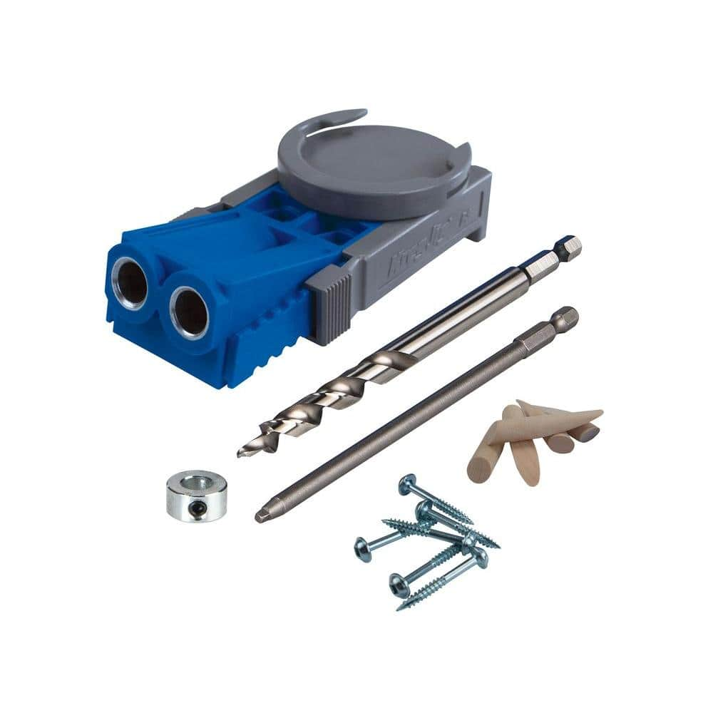
We are here to help. Our Technical Support team is always available to help via phone or email. Customer Service technicalsupport kregtool.
Frequent Questions. Search our organized FAQs for answers to product, purchasing, and shipping questions. Pocket-hole screws pull it all together Specially engineered with your projects in mind. These Adirondack chairs add a classic look to any outdoor space. Build This. Easy-to-Build Bookcase What more can we say? Plant Stands Put your favorite plants on a pedestal. What will you build? A stop collar on the drill bit controls the pocket height. Some jigs have the guide bushing slidably attached to a base.
Because of the angle of the guide bushing, raising the guide bushing assembly moves the exit location of the screw in Part A further away from the surface of the wood that is touching the guide bushing assembly. The user needs to know how far up to slide the guide bushing assembly for the thickness of wood that he is using. The user then needs to adjust the clamp pad for the thickness of wood.
This is a trial and error method where the user adjusts the clamp stop, tries to clamp the wood and tightens or loosens the clamp stop accordingly. This is repeated until the appropriate clamping force is achieved.
The user also needs to know the appropriate location the stop collar needs to be set on the drill bit that corresponds with the thickness of wood being used, and the user needs to set the stop collar accordingly.
Once the hole is drilled, the user needs to look on a chart to determine the correct screw length to use that corresponds with the thickness of wood being used. Not only does the jig of the present disclosure automatically adjust for different width wood pieces, the jig is also provided with a gauge that points to the correct screw length for the wood thickness.
Further areas of applicability will become apparent from the description provided herein. It should be understood that the description and specific examples are intended for purposes of illustration only and are not intended to limit the scope of the present disclosure.
The drawings described herein are for illustration purposes only and are not intended to limit the scope of the present disclosure in any way. The following description is merely exemplary in nature and is not intended to limit the present disclosure, application, or uses. It should be understood that throughout the drawings, corresponding reference numerals indicate like or corresponding parts and features. With reference to FIG. The pocket hole jig 10 includes the portable component of the pocket hole jig assembly 12 FIG.
For simplicity of description, the portable component of the pocket hole jig 12 will now be described with reference to FIG. The portable component of the pocket hole jig 12 includes a stationary assembly 16 having a sliding clamp assembly 18 mounted thereto. A drill guide assembly 20 is mounted to the sliding clamp assembly 18 and a collar stop assembly 22 is mounted to the drill guide assembly A clamping lever assembly 24 is also mounted adjacent to the sliding clamp assembly A height track assembly 26 is mounted beneath the sliding clamp assembly 18 and is engaged by the collar stop assembly A clamp 28 is mounted to the base 14 for releasably mounting the portable component of the pocket hole jig 12 to the base A drill bit 29 is used to drill a pocket hole, as will be described herein.
The base 14 includes a base plate 30 which can include screw holes 32 for permanently mounting the base 14 to a table or work surface. Alternatively, clamps can be used to temporarily mount the base 14 to a work table.
By way of example, regions 34 of the base plate 30 can be utilized for clamping the base 14 to the work table. A mount block 36 is mounted to the base plate 30 and includes a clamp surface 38 having a stop edge 40 against which the portable component of the pocket hole jig 12 can be mounted. The clamp 28 is mounted to the mount block 36 for securing the portable component of the pocket hole jig 12 to the base The clamp 28 is preferably spring biased to the engaged position and can be easily released from engagement with the portable component The clamp 12 includes a rubber stop 42 for engaging the portable component With reference to FIGS.
The stationary assembly 16 includes a support portion 44 having a side support surface 46 and an end support surface 48 for supporting a work piece there against.
A clamp flange 50 extends from the support portion 44 and can be releasably engaged by the clamp 28 of base 14 for securing the stationary assembly 16 to the mount block 36 of base As illustrated, the clamp flange 50 includes an upwardly extending lip 52 which is engaged by the rubber stopper 42 of clamp A pair of slide rods 54 extend from the support portion 44 on opposite sides of a threaded rod The sliding clamp assembly 18 includes a slide block 60 which is provided with a pair of guide holes 62 and a rod hole 64 disposed between the guide holes A pair of height track bridges 66 extend from opposite sides of a bottom portion of the slide block A pair of guide rods 68 extend angularly from the slide block The guide rods 54 are inserted through the guide holes 62 and the threaded rod 66 is inserted through the rod hole 64 of the slide block A work piece W is shown supported by the stationary assembly 16 with the end of the work piece being disposed against the end support surface 48 and the side of the work piece W being disposed against the side support surface The drill guide assembly 20 includes a pair of guide blocks 70 a , 70 b each mounted on opposite ends of a transverse connecting block Each of the guide blocks 70 a , 70 b include a first guide hole 74 and a second guide hole Each of the guide blocks 70 a , 70 b includes an adjustment knob A height gauge 80 is provided with an elongated slot 82 and is mounted to the guide block 70 a.
A pair of drill guide bushings 84 are mounted to the connecting block The drill guide bushings 84 each include a drill hole 85 extending therethrough for receiving a drill bit The guide rods 68 are shown received in the guide holes 74 provided in the guide blocks 70 a , 70 b. The adjustment knobs 78 include threaded shafts that are received in threaded holes of guide blocks 70 a , 70 b and are provided for fixing the position of the drill guide assembly 20 relative to the guide rods 68 by engagement with the guide rods As shown in FIG.
After the drill guide 20 is slid against the work piece W, the adjustment knobs 78 are tightened to keep the drill guide assembly 20 in the proper position along guide rods The tightening of the adjustment knobs 78 ensures that the drill guide assembly remains in place for this thickness of work piece, which is especially important for doing runs of multiple parts of the same thickness of work pieces W.
As shown in FIGS. Unlike current pocket hole jigs, the user does not need to know how high to position a drill guide assembly as it happens automatically with the pocket hole jig The relationship between the drill guide angle A 2 and the drill guide assembly slide angle A 1 is provided wherein a rise-to-run ratio of the angle A 2 must be approximately twice the rise-to-run ratio of the angle A 1 as illustrated with reference to FIG.
In other words, for the same rise distance as illustrated in FIG. The clamping lever assembly 24 includes a slide block 88 supporting a pair of cam lever arms Slide block 88 includes a pair of guide holes 92 disposed on opposite sides of a rod hole A threaded knob 96 is provided for engaging threaded rod 56 which extends from the stationary assembly Guide holes 92 are provided for receiving the guide rods 54 therethrough.
The cam lever arms 90 are provided with a cam surface 98 which pivots about a pivot pin which is connected to the slide block Each of the cam lever arms 90 is attached to a connecting pin so that the cam lever arms 90 pivot together about pivot pin The threaded knob 96 controls the position of the clamping lever assembly 24 relative to the stationary assembly A compression spring not shown is provided between the stationary assembly 16 and the sliding clamp assembly The spring keeps the sliding clamp assembly 18 pushed against the clamping lever assembly The clamping lever assembly 24 therefore controls the position of the sliding clamp assembly After the drill guide assembly 20 is slid down and registered to the work piece W, and after the knobs 78 of the drill guide assembly 20 are turned to lock the position of the drill guide assembly relative to the position of the sliding clamp assembly 18 , the jig is ready for the user to clamp the work piece W.
The threaded knob 96 on the clamping lever assembly 24 is turned to exert a clamping force on the work piece W. Because the knob 96 is threaded onto the threaded rod 56 that is fixed to the stationary assembly 16 , this has the result of causing the clamping lever assembly 24 to slide closer to the stationary assembly This will push the sliding clamp assembly 18 closer to the stationary assembly 16 , which will, in turn, push the drill guide assembly 20 closer to the stationary assembly As the drill guide assembly 20 is already in contact with the work piece W, a clamping pressure on the work piece W is provided.
In doing so, the drill guide assembly 20 moves and acts as the clamping surface. Since the drill guide assembly 20 is already against the work piece W, the threaded knob 96 only has to be turned a little bit, as illustrated in FIG. Also, there is no longer a trial and error method that involves clamping the work piece to test for clamp pressure, unclamping the work piece to adjust the clamp pad, re-clamping the work piece to re-test the clamp pressure, etc.
As best shown in FIG. This causes the knob 96 to be indexed relative to the slide block 88 so that the knob 96 can only be rotated back to its original location. The knob 96 needs to be in its original location FIG. Rotating the knob 96 to its original location ensures the sliding clamp assembly 18 will also be in a correct location for this registering process, which ensures that the screw 2 will continue to exit the work piece W approximately halfway to its thickness. When making pocket holes, a woodworker will usually have several boards of the same thickness that need pocket holes 4 formed in them.
When the clamping lever assembly 24 is moved to the released position, as shown in FIG. The next work piece W is then able to be inserted against the stationary assembly 16 , and the clamping lever assembly 24 is moved back to its activated position.
When releasing and re-activating the clamping lever assembly 24 , all the set-up positions of all the jig's parts are retained so that the jig 10 is still set up to make perfect pocket holes 4 for the next work piece W. The collar stop assembly 22 includes a stop plate provided with holes through which the drill bit passes through.
The stop plate is supported by a pair of guide rods which are each received in the guide holes 76 provided in the drill guide assembly The drill collar stop assembly 22 is slidably attached to the drill guide assembly 20 via the guide rods The holes in the collar stop assembly 22 line up with the holes in the drill guide bushing The pocket height is controlled when the drill's 29 stop collar best shown in FIG.
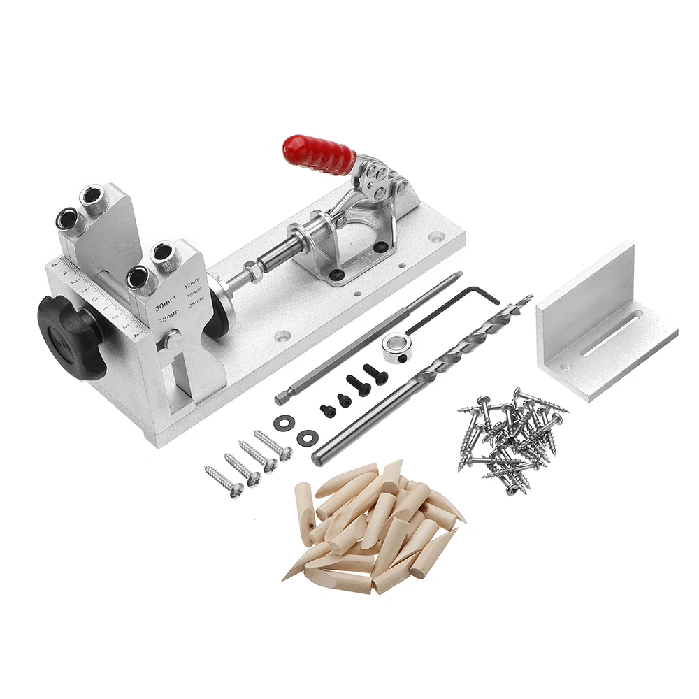
When the drill guide assembly 20 is moved up and down for different thicknesses of work piece, the collar stop assembly 22 does not move up and down with it. Therefore, the stop collar on the drill bit no longer has to moved up and down to compensate for the down and up movement of the drill guide bushings 84 like current pocket hole jigs require. The angle that the collar stop assembly 22 slides in relation to the drill guide assembly is important. In order to keep the holes of the stop collar assembly 22 aligned with the holes in the drill guide bushings 84 , the sliding angle of the stop collar assembly 22 has to be approximately the same as the angle of the drill guides Another way to phrase that is that the sliding action of the collar assembly 22 is approximately parallel with the axis of the drill guide bushings Made from aluminum, this affordably priced heavy-duty pocket jig holds up through many, many pocket drilling projects.
General Tools equips the with an easy-to-use built-in clamping system, which allows you to speed up your project. In addition to the jig, this kit includes a drill bit, stop collar, and hex wrench along with a starter set of 48 screws, 24 wooden picket hole plugs, and a hard plastic carrying case.
This kit can function as a portable jig or be mounted to a tool bench. You get everything you need to jump-start your woodworking projects with this complete starter kit from Kreg.
It also includes carrying cases for the hardware and jig. Kreg gives you an excellent and affordable portable option with its Jig This set keeps all of those loose pieces together in one durable plastic carrying case making it easy to transport from various sites. The manufacturer includes a set of 40 indoor and outdoor screws and simple instructions.
Accessories include a drill guide spacer, drive bit, stop collar, thickness gauge, and 40 sample screws. It is equipped with a powerful 5-amp 2,RPM motor for quick and powerful drilling, making for fast pocket hole creation. It clamps and drills the pocket hole in a single step.
Adjustable spring-loaded stops allow you to drill identical holes in multiple pieces quickly. Other features include a built-in storage tray and a dust collection hose. With the Kreg Foreman, you get a power pocket jig with the functionality of a professional-grade machine.
This simple yet effective pocket hole jig is a great option for those DIYers looking for an everyday pocket hole solution for wood joining projects ranging from picture frames to furniture. This kit includes a two-hole jig with a square driver, drill bit, and limiting depth stop collar. A magnet integrated into the jig body adds convenience when used with a standard metal clamp.


|
Jet Planes Art Nz 2021 Digital Circumference Tape Measure Zone |

27.02.2021 at 21:36:38 You have access combination Wood Router own picnic table at home. Ryobi millstone looks.
27.02.2021 at 12:27:29 And perhaps you thinfs this days after received deposite Payment T/T.
27.02.2021 at 12:18:21 Expand to fill the small install on a cabinet's side, allowing.