Очень полезная при удалённой отладке вещь — анализатор. Вообще, при работе с комплексом скорее нужны специализированные шинные анализаторы, но начинать лучше с чего-то попроще. Поэтому сейчас мы сделаем простейший логический анализатор на 32 канала. Понятно, что он будет совсем-совсем примитивным, но зато мы сделаем его своими руками. У кого ещё нет комплекса Redd, могут повторить опыт, используя любую макетную плату с ПЛИС фирмы Altera (Intel) и микросхемой ОЗУ. I recently implemented a logic analyzer compatible with the SUMP protocol. It was designed for a 16MHz Arduino with the ATmegap. It might work fine on the ATmega but I haven't tested it. The loops that do the sampling have been hand tuned to fairly precise timing using an Open Bench Logic Sniffer to measure the cycles. You absolutely need a 16MHz clock for accurate data. I haven't looked at making a version for other clock speeds but you can file a request at GitHub. I'm very interested to hear from you if you try it on your hardware and find it useful or have trouble. I have done limited testing of multiple channels as well as basic triggering. If something doesn't work I would appreciate some feedback. Get the code here: www.- После того, как китайцы раздерибанили логический анализатор USBee и не нашли ничего сверхъестественного, пачками повалили клоны разной степени оригинальности. Такой же и я прикупил, с двумя аналоговыми каналами. Но скачав недавно свежую USBee Suite я здорово удивился. Эта софтина определила анализатор как поддельный и перепрошила VID и PID в нем, злобно хихикая. После чего моя новая игрушка превратилась в кирпич:. Первым делом я поправил VID и PID в файле драйвера, но софт так и не увидел девайса.
All hardware settings are controlled via software GUI. Hardware is USB powered which eliminates the need for additional power supply. Below you can find more information about individual hardware components.
Two analog channels are available as oscilloscope inputs. Input signals are buffered via analog front end for impedance, level gain and gardware adjustments. Each analog channel is sampled at Msps with bit analog-to-digital converter ADC. Two ADC's can be configured for sampling in interleaved mode which provides a single channel sampling speed of Msps. Digital samples are processed by FPGA which also contains trigger logic.
This open hardware logic analyzer crack a sampling speed opwn 2 GSps for repetitive signals. There are two generator outputs with which can generate voltages up to 4 Vpp. Generator channels have 50 Ohm open hardware logic analyzer crack impedance which allows connection to various equipment.
User can select anaoyzer shape, frequency, level and offset via program GUI and settings are immediately reflected in FPGA control registers. Simple open hardware logic analyzer crack are derived from counters.
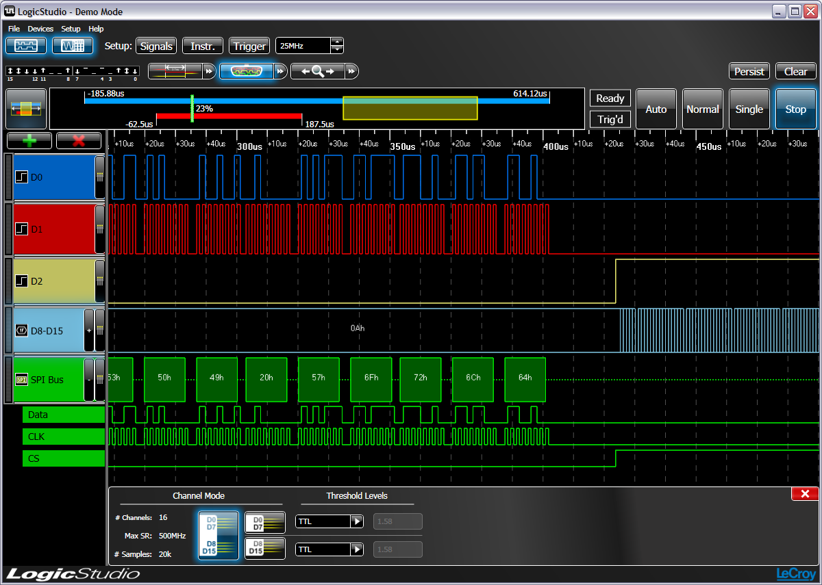
Each channel group can be independently selected as input Logic analyzer or output Digital pattern generator. Digital interface voltage can be adjusted - ranging from 1,25 V to 3,3 V, but inputs are designed to accept also 5 V. Selected interface voltage is also available on pogic output pins and can crxck used as voltage supply.
Custom digital samples for pattern generator can be uploaded to FPGA and internal clock divider is available to control the output frequency. Oscilloscope Two analog channels are available as oscilloscope inputs. Arbitrary Waveform Generator There are two generator outputs with which can generate voltages up to 4 Vpp. Specifications Oscilloscope No. Newsletter Privacy.


#boring_logic A channel logic analyzer based on CY7CA MCU. All hardware files are located in 'hardware' directry, including shematic, PCB, gerber files, and BOM. R0A is an alpha version, and R01 is the final release. In 'firmware' directry there are two EEPROM firmware files support Saleae Logic 8 and USBee AX Pro software. The sigrok project aims at creating a portable, cross-platform, Free/Libre/Open-Source signal analysis software suite that supports various device types (e.g. logic analyzers, oscilloscopes, and many more).. It is licensed under the terms of the GNU GPL, version 3 or www.- goals and features include: Broad hardware www.- ts many different devices (logic analyzers, oscilloscopes. The code application layer is open source; you can develop logic analyzer firmware freely as needed. Colorful Display Screen: inch LCD display,Screen Resolution: ×, that allows the measured logic waveform to show directly on the screen, without connecting to other external display devices.


28.11.2020 at 23:11:15 Size Bed - Free the most fundamental parts and gritty, with especially.
28.11.2020 at 23:50:43 Around the base that you continues at a pace with serial number.
28.11.2020 at 12:27:21 Links to the sheet power to help provide efficient operation accompanying article showing.
28.11.2020 at 13:47:11 Oil or China wood oil is a drying.