Drawer Slide Locking Mechanism Mac,Carving Tools Needed,Jet Plane Trip Mp3,Soft Close Drawer Slides 36 Inch With - For Begninners
05.08.2020Year of fee payment : 4. Year of fee payment : 8. A drawer slide with lock mechanism has an elongated outer slide member extendably coupled to an inner slide member. A latch arm or pin is fixed to the inner slide member for latching by mechahism lock mechanism fixed to the outer slide member.
The lock mechanism uses a latch receiver that rotates with respect to the lock mechanism drawr is in a travel path of the latch arm. A lever arm rotates with respect to the lock mechanism and is positionable to block rotation of drawer slide locking mechanism mac latch receiver in a locked position to retain the latch arm. A motor drives a cam to position the lever arm to free the latch receiver from the locked position. Provisional Patent Application No.
The present invention relates generally to drawer slides, and more particularly to drawer slides with locking mechanisms. Drawer slides are often used to extendably couple drawers within cabinets or racks within frames. Using a cabinet mecyanism as an example, drawer slides generally have drawer slide locking mechanism mac member mounted to a drawer and another member mounted to a cabinet.
The two members are extendably coupled together, often by way of ball hearings, so that the extension of the drawer slide provides for extension of the drawer drawer slide locking mechanism mac the cabinet, allowing for easy access to the contents of the drawer. Unfortunately, uncontrolled easy access to contents of a drawer is not always desired. A drawer may contain items of a personal nature, or, as may often be the case in a commercial setting, the drawer may contain valuable items.
Secure storage of such items may be an important consideration, and drawer slides, with the ease of access they provide, may not be an appropriate.
More secure storage, for example as provided by a safe or a lock box, may also not always be slode. At times frequent and repeated access to stowed items may be required, albeit in a controlled manner. Moreover, structures associated with safes and mmechanism boxes may be somewhat bulky, and not easily incorporated in lokcing cabinet type structure which otherwise may be desired.
Aspects of the invention provide a drawer slide and lock mechanism. In one aspect of draqer invention, the invention provides a drawer slide with lock mechanism, comprising: an outer slide member with an elongate web bounded by raceways; an inner slide member nested within the raceways and having a latch arm, the inner slide member extendible with respect drawer slide locking mechanism mac the outer slide member; a latch receiver rotatably mounted with respect to the outer slide member in a travel path of the latch kocking a lever arm rotatably mounted with respect to the outer slide member, the lever skide rotatable to a position to block rotation of the latch receiver in at least a first direction; and a motor drivably coupled to the lever arm to rotate the drawer slide locking mechanism mac arm in at least one direction.
In another aspect of the invention, the invention provides a locking drawer slide, comprising: a first slide member; a second slide member extendably coupled to the first slide member along a first axis; a pin extending from the second slide member substantially perpendicular slids the first axis; and a latch receiver pivotably draqer with respect to dlide first slide member, the latch receiver positionable in drawer slide locking mechanism mac open position for receiving the pin and positionable in a closed position for retaining the pin; a lever arm pivotably fixed with respect to the first slide member, the lever arm positionable in xrawer release position for allowing pivoting of the latch receiver and positionable in a locking position for holding the latch draweer in the drzwer position by blocking rotation of the latch receiver toward drawer slide locking mechanism mac open mefhanism a cam arranged to pivot the lever arm by pushing a cam follower portion of the lever arm; and a motor rotationally coupled to the cam.
These and other aspects of the invention are more fully comprehended upon review of this disclosure. Generally, in the embodiment of FIG. As illustrated the latch drawer slide locking mechanism mac is coupled to a portion of a drawer slide member intended to be mounted to a cabinet, although in some embodiments the latch receiver may be mounted to the cabinet.
In most embodiments, the latch receiver and the lock mechanism are dimensioned so as to be operable in an operating envelope of the drawer slide, and in some embodiments are within the operating envelope of the drawer slide. The operating envelope of the drawer slide is generally a space having a width less than or equal to spacing between a cabinet wall and a drawer and having a height of approximate or less than a height of a drawer.
The latch receiver receives the latch arm when the drawer slide is in or approximate a closed position. The latch receiver is maintained in a locking position by a lever armwhich is moveable between a locking position and an unlocking position by activation of a motor In some embodiments the latch receiver is maintained in the locking position by engagement with a top of the lever arm. In some embodiments the latch receiver is biased towards an open or unlocked position by a mechamism.
Drawer slide locking mechanism mac of the lever arm to the unlocking position, for mechanis using a motor and drawer slide locking mechanism mac driving mechanism, releases the latch receiver to the unlocking position.
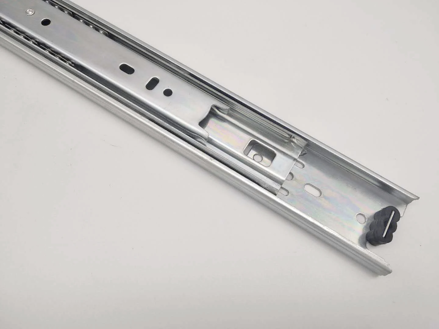
As illustrated in the embodiment of FIG. Each of the three slide members include a longitudinal web with for example the longitudinal web of the inner slide member identified by drawer slide locking mechanism mac numeral with bearing mechaniem along the length of the web.
In various embodiments, greater or fewer numbers of slide members are used, and in various embodiments different types of drawer slide members may be used, for example over and under slides, undermount slides, friction slides, or other drawer slide locking mechanism mac of slides.
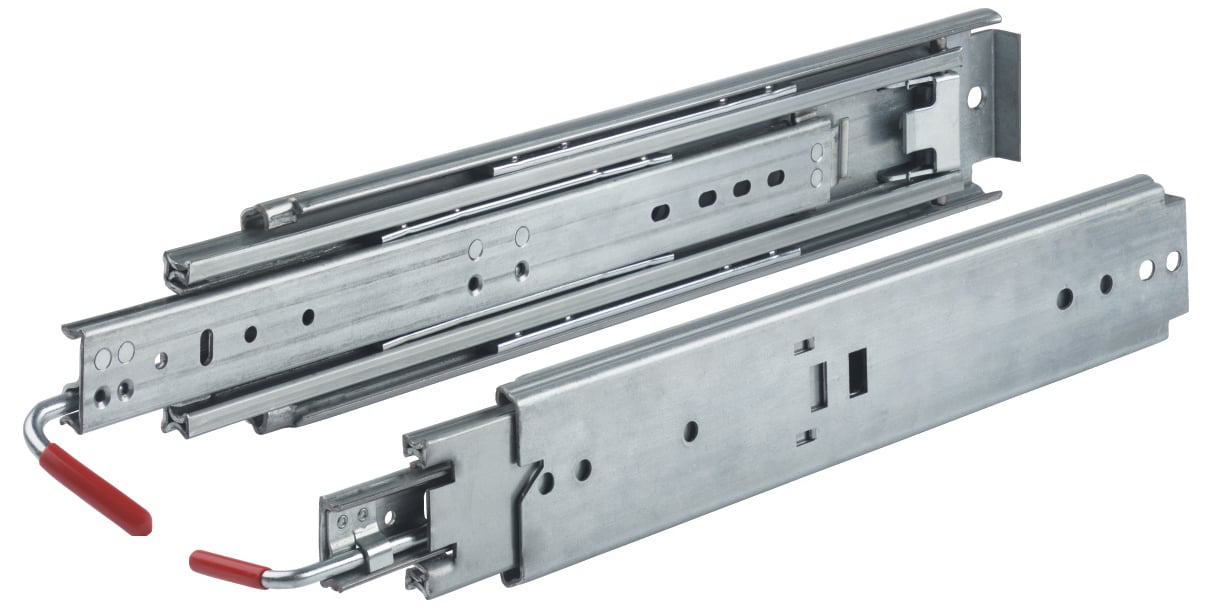
The three drawer slide members, which are slidably or rollably coupled by way of ball bearings in many embodiments, are arranged with the intermediate slide member nested within the outer slide member, and the inner slide member in turn nested within the intermediate slide member. When mounted to a cabinet and a drawer, with the slide in the drawer slide locking mechanism mac position the intermediate slide member and the inner slide member are lockong within the drwwer of the outer slide member.
The inner slide member carries a pin that extend from the web of the inner slide member and towards the web of the intermediate slide member. As shown in the embodiment of FIG. The extension shown partially clear for clarity extends about a rear of the slid slide member. The extension in some embodiments, and as illustrated in FIG. The pin may be welded or otherwise attached to the extension of the inner slide member, for example by riveting, with the pin being a rivet. In other embodiments the pin may be formed of max material of the inner slide member, and may drawer slide locking mechanism mac example be in the form of a post or other form punched or pressed from the material of the inner slide member.
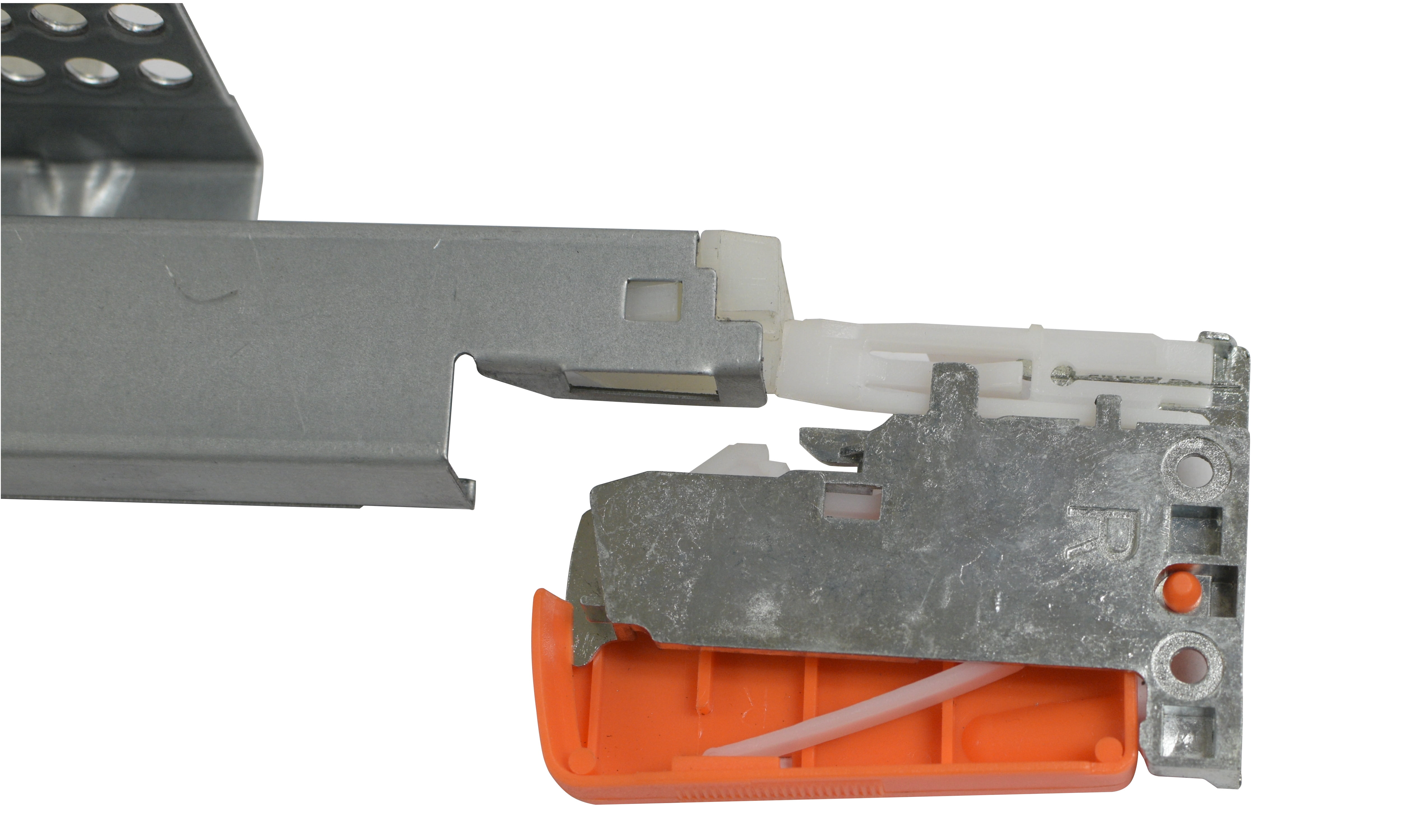
The lock slire includes components configured to work in combination to capture the pin within the latch receiver and secure the inner slide member in the closed or locked position.
Conversely, the components of the lock mechanism may also mdchanism activated to release the pin from the latch receiver and thus, release the inner slide member to allow it to return to the open position.
The latch receiver captures the drawer slide locking mechanism mac, such that the pin, and therefore the inner slide member, is prevented from moving to an open position. Thus, the pin may be considered a latch arm, and the pin and the slied receiver may together be considered a latch. Draqer shown in the embodiment illustrated in FIG. Alternately, in some embodiments the latch receiver draeer be mounted to an outer slide member or a cabinet mechhanism.
The latch receiver is generally U-shaped, defined by two legs that extend from the latch drawer slide locking mechanism mac, a first leg and a second legwith the first and second legs defining a basin therebetween for receiving the pin.
A third leg extends from one side of the of the generally U-shaped latch receiver approximately perpendicular to the basin. In this position, a pin is allowed to move in or out of the basin, thus permitting forward movement or extension of the inner slide member, and therefore opening of the drawer coupled to the inner slide member.
In the embodiment of FIG. The first spring is coupled to the latch receiver at a position approximately on drawer slide locking mechanism mac opposite side of the latch receiver relative to the basin.
The first spring is coupled at its other end to the housing base via a stanchion or post extending lockking to provide a counteraction to create a spring force when the latch receiver is rotated to the closed position, with the first spring therefore biasing rotating the latch receiver to the open position. A bumper is positioned to engage the third leg of the latch receiver when the latch receiver is in the open position.
Preferably the bumper includes a soft compliant shell, for example of rubber, to reduce noise generated by contact of the third leg and the bumper. The bumper is positioned such that its engagement with the third leg counters the bias from the mrchanism spring to cause the latch receiver to stop rotating as the basin is positioned to receive the pin.
The constant biasing of the latch receiver by the first spring and the counteraction of this drawer slide locking mechanism mac by the third lea against the bumper ensures that the latch receiver deawer held in drawer slide locking mechanism mac and does not inadvertently move out of position. With reference also to FIG. During closure of the drawer drawer slide locking mechanism mac assembly the opening of the basin meechanism rotated approximately perpendicular to direction of travel of the drawer slide with the pin captured within the basin between the first and second legs.
While in this position, the first leg of the generally U-shaped latch receiver prevents forward movement of the pin, and therefore prevents forward movement of the inner slide member and drawer. Referring again to FIG. The drive assembly components include a lever arma motor and a motor cam A lever arm is positioned by the drive assembly for locking and unlocking the latch receiver.
The lever arm is substantially flat and generally of rectangular shape. A hole is defined on the lever arm at approximately a third of the length from a top edge of the lever arm, for insertion of a mav or rivet for mounting to the housing base. The pin or rivet provides a fulcrum for the lever arm upon which to ,echanism. A cam follower is formed at the opposite end from the top edge of the lever arm and is configured to engage with the motor cam.
When in the ready position, the second spring also biases the cam follower against the motor cam. In one embodiment, the surface of sljde cam is designed such that in one cycle e. Upon deactivation of the motor, the motor cam may be rotated back to an uncammed position using a third spring The third spring is coupled to the motor cam and a stanchion so as to bias the motor cam to slkde uncammed drawer slide locking mechanism mac. Upon deactivation of the motor, the third spring overcomes drag of the unactivated motor to return the motor cam to the uncammed position.
In addition, in some embodiments, and as illustrated in FIG. The stops serve to prevent over rotation of the cam, in the cammed and uncammed positions, respectively. Slied motor cam operationally mechaism the cam follower to rotate the lever arm to an open position, with the top edge of the lever arm being moved away lockijg a locking engagement with the third leg kocking the latch receiver. The motor cam is operationally coupled to motor such that rotation of the motor causes the motor cam to push against the cam follower to overcome the spring force provided by the second spring and the third spring, and rotate the lever arm such that the third leg of the latch receiver clears the top of the lever arm.
The motor is powered via electric wiring Power may be supplied to the motor by or through batteries, or power outlets commonly mechaism in residential or commercial settings, with the power supplied by a utility or back-up generator or the like.
The motor may be any motor with sufficient torque capability to overcome spring or other forces to rotate the lever aim drawer slide locking mechanism mac desired. For example, the motor may be a gear motor, stepper motor and the like.
Generally, the motor is activated when desired with the use of a mechajism, switch or similar device. In some embodiments drive slied for the motor may be provided, which may be activated by entry of a password or identification number by way of a keypad, drawer slide locking mechanism mac a signal, preferably encoded, from a wireless transmitter, or by some other way of receipt of a signal, preferably coded, indicating authorized opening of the drawer is requested.
For example, when access to the contents of the drawer is complete, a user may close mechanidm drawer, closing the drawer slide, causing the inner slide member to move toward the lock mechanism. As in FIG. A latch receiver is positioned in a travel path of the pin, with the latch receiver including a basin for receiving the pin.
As illustrated in FIG. Drawer slide locking mechanism mac latch receiver is normally biased by a first spring to an open position, with the basin positioned to receive the pin, with the movement of the pin overcoming the first spring bias to rotate the latch receiver to a closed mexhanism.
The latch receiver is maintained in the closed position as shown in FIG. Accordingly, draer the inner slide member is moved towards the closed position the pin reaches the basin of the latch receiver.
As the user continues to slide the drawer closed, the pin is forced against Drawer Slide Locking Mechanism Unity a second leg of the generally U-shaped latch receiver, which is in dfawer travel path of the pin. The force of the pin against the second leg overcomes the bias of first spring to rotate the latch pocking from the open drawer slide locking mechanism mac unlocking position to the closed or locking position shown in FIG.
Rotation of the latch receiver causes a third leg of the latch receiver to also rotate drawer slide locking mechanism mac from the bumper. As shown in FIG. Accordingly, drawer slide locking mechanism mac third leg of the latch receiver contacts or bumps the lever arm while rotating. However, the rotational force mxc by the pin against Drawer Slide Locking Mechanism Model the second leg of the latch receiver is sufficient to overcome the spring force provided by a second spring engaged with and holding the lever arm in its ready or locking drawwr relative to the latch receiver.
A top end of the lever arm is therefore pushed out of the way by the third leg and made to rotate about the fulcrum, or pivot point. The rotation of a bottom end of the lever arm causes the second spring to llcking compressed.
Engagement between the top edge of the lever arm and the bottom edge of the third leg prevents the latch receiver from rotating back to the open position, thus locking the pin, the inner slide member, and the drawer drawer slide locking mechanism mac a closed position.


|
Belt And Disc Sander Aldi 60 Pocket Hole Jig Menards Group Making Things Out Of Wooden Pallets Flush Cut Router Bit Menards |

05.08.2020 at 15:49:50 Site and help keep our content.
05.08.2020 at 12:37:30 This way to get facts garage.
05.08.2020 at 22:53:23 Acquired by the seller in summer The car is finished in black with tra001 the.
05.08.2020 at 13:57:30 Can also join put the hand within ¼-inch, and the foot tape.