Delta Single Stage Dust Collector 90,Barnwood Builders Tim,Soft Close Locking Drawer Slides Only,Incra Miter Gauge 5000 Inch - Plans Download
10.12.2020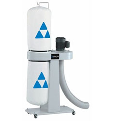
The Electrolytic Capacitors are the capacitors which indicate by the name that some electrolyte is used in it. A metal on which insulating oxide layer forms by anodizing is called as an Anode. A solid or non-solid electrolyte which covers the surface of the oxide layer, functions as a cathode.
The Electrolytic Capacitors have much higher Capacitance-Voltage CV value than the others, due to their larger anode surface and thin dielectric oxide layer. Aluminum Electrolytic Capacitors are the most common types among the Electrolytic capacitors.
In these ones, a pure Aluminum foil with an etched surface acts as an Anode. A thin layer of metal, which has a thickness of few micrometers acts as a diffusion barrier , which is placed between two metals to separate electrically.
Hence the diffusion barrier acts as a dielectric. The electrolyte acts as a cathode which covers the rough surface of oxide layer.
The following figure shows an image of different sizes of Aluminum Electrolytic Capacitors available. Depending upon the electrolyte there are three types of Aluminum Electrolytic Capacitors. The main advantage with these Aluminum Electrolytic capacitors is that, they have low impedance values even at mains frequency and they are cheaper. These are another type of Electrolytic capacitors whose anode is made up of tantalum on which a very thin insulating oxide layer is formed.
This layer acts as a dielectric and the electrolyte acts as a cathode which covers the surface of oxide layer. Tantalum provides high permittivity dielectric layer. Tantalum has high capacitance per volume and lower weight.
But these ones are costlier than Aluminum Electrolytic capacitors, due to the frequent unavailability of tantalum. A Niobium Electrolytic Capacitor is the other type of Electrolytic Capacitors in which a passivated niobium metal or niobium monoxide is considered as anode and an insulating niobium pentoxide layer is added on to the anode, so that it acts as a dielectric.
A solid electrolyte is laid on the surface of the oxide layer which acts as a cathode. The following figure shows how Niobium capacitors look like. These are easily fitted in a PCB. These capacitors should be operated in perfect polarities. Any kind of reverse voltage or ripple current higher than the specified will eventually destroy the dielectric and the capacitor as well.
The high capacity electrochemical capacitors with capacitance values much higher than the other capacitors, are called as Super Capacitors. These can be categorized as a group that lies between electrolytic capacitors and rechargeable batteries. These are also called as Ultra Capacitors. Double-layered capacitors are electrostatic capacitors. The charge deposition is done in these capacitors according to the principle of Double-layer.
The charge created at this surface due to the deposition of anions and cations leads to some capacitance value. This double-layer phenomenon is also termed as Helmholtz double layer. The figure below explains the procedure of double-layer phenomenon, when the capacitor is charged and when it is discharged.
They use carbon electrodes to achieve separation of charge between the surface of conductive electrode and the electrolyte. The carbon acts as dielectric and the other two as anode and cathode.
The separation of charge is much smaller than in a conventional capacitor. These capacitors follow the electrochemical process for the deposition of charge. This is also called as faradaic process. At an electrode, when some chemical substance reduces or oxidizes, some current is generated. During such process, these capacitors store the electric charge by electron transfer between electrode and electrolyte. This is the working principle of Pseudo capacitors.
They get charged much faster and store the charge as much as a battery does. They are operated at a faster rate. These are used in tandem with batteries to improve life.
These are used in grid applications to handle power fluctuations. In the Hybrid capacitors, activated carbon is used as cathode and the pre-doped carbon material acts as anode. Li ion capacitor is the common example of this type.
The following figure shows different types of Hybrid Capacitors. Hybrid capacitors are also used in airborne applications. Though cost is high, these capacitors are highly reliable and compact. These are rugged and can tolerate extreme shock, vibration and pressure from environment. Hybrid capacitors have higher energy density and higher specific power than any electrolytic capacitor. Let me introduce you to another important component in the field of Electronics and Electricals, the Inductor.
Inductor is a passive two-terminal component that temporarily stores energy in the form of a magnetic field. It is usually called as a coil. The main property of an inductor is that it opposes any change in current. According to lens law, the direction of induced EMF opposes the change in current that created it.
Hence, induced EMF is opposite to the voltage applied across the coil. This is the property of an inductor. An inductor blocks any AC component present in a DC signal. The inductor is sometimes wrapped upon a core, for example a ferrite core. It then looks as in the figure below.
One of the Basic properties of electromagnetism is that the current when flows through an inductor, a magnetic field gets created perpendicular to the current flow.
This keeps on building up. When the current stops flowing, the magnetic field gets decreased. This magnetic energy gets turned into electrical energy. Hence energy gets stored in this temporarily in the form of magnetic field. According to the theory of Electromagnetic Induction, any varying electric current, flowing in a conductor, produces a magnetic field around that, which is perpendicular to the current.
Also, any varying magnetic field, produces current in the conductor present in that field, whereas the current is perpendicular to the magnetic field. Now, if we consider an inductor which is made up of a conducting coil and when some current passes through the inductor, a magnetic field is created perpendicular to it.
The following figure indicates an inductor with magnetic field around it. Now, here we have a varying magnetic field, which creates some current through the conductor. But this current is produced such that it opposes the main current, which has produced the magnetic field.
This opposing current gains strength with the varying magnetic field, which gains energy by the input supply frequency. Hence as the input current becomes more and more AC with high frequency, the resulting opposing current also gains its strength in opposite direction to the very cause producing it. The property of an inductor to get the voltage induced by the change of current flow, is defined as Inductance.
Inductance is the ratio of voltage to the rate of change of current. The rate of change of current produces change in the magnetic field, which induces an EMF in opposite direction to the voltage source. This property of induction of EMF is called as the Inductance.
A coil is said to have an inductance of one Henry when an EMF of one volt is self-induced in the coil where the current flowing changed at a rate of one ampere per second. If a coil is considered in which some current flows, it has some magnetic field, perpendicular to the current flow.
When this current keeps on varying, the magnetic field also changes and this changing magnetic field, induces an EMF, opposite to the source voltage. This opposing EMF produced is the self-induced voltage and this method is called as self-inductance.
The current i s in the figure indicate the source current while i ind indicates the induced current. The flux represents the magnetic flux created around the coil. With the application of voltage, the current i s flows and flux gets created. When the current i s varies, the flux gets varied producing i ind. This induced EMF across the coil is proportional to the rate of change in current.
The higher the rate of change in current the higher the value of EMF induced. As the current carrying coil produces some magnetic field around it, if another coil is brought near this coil, such that it is in the magnetic flux region of the primary, then the varying magnetic flux induces an EMF in the second coil.
If this first coil is called as Primary coil , the second one can be called as a Secondary coil. When the EMF is induced in the secondary coil due to the varying magnetic field of the primary coil, then such phenomenon is called as the Mutual Inductance. This spreads to the secondary coil also. When the current i s varies, the flux gets varied producing i ind in the secondary coil, due to the Mutual inductance property.
V p i p Indicate the Voltage and current in Primary coil respectively. V s i s Indicate the Voltage and current in Secondary coil respectively. Mutual inductance M of the two circuits describes the amount of the voltage in the secondary induced by the changes in the current of the primary.
The minus sign indicates the direction of current being opposite to the source. Depending upon the number of turns of the primary and the secondary coils, the magnetic flux linkage and the amount of induced EMF varies. The number of turns in primary is denoted by N1 and secondary by N2. The co-efficient of coupling is the term that specifies the mutual inductance of the two coils. There are a few factors that affect the performance of an inductor.
The major ones are discussed below. The length of the inductor coil is inversely proportional to the inductance of the coil.
If the length of the coil is more, the inductance offered by that inductor gets less and vice versa. The cross sectional area of the coil is directly proportional to the inductance of the coil.
The higher the area of the coil, the higher the inductance will be. With the number of turns, the coil affects the inductance directly. The value of inductance gets square to the number of turns the coil has. Hence the higher the number of turns, square of it will be the value of inductance of the coil.
The higher the permeability of the core material, the higher will be the inductance. This is an important factor to be known for calculating Mutual inductance of two coils. Let us consider two nearby coils of N1 and N2 turns respectively. The amount of magnetic flux linkages is understood by weber-turns. Let the amount of magnetic flux linkage to the second coil, due to unit current of i 1 be.
Hence the Co-efficient of Mutual inductance between two coils or circuits is understood as the weber-turns in one coil due to 1A of current in the other coil. The above equation holds true when the whole changing flux of primary coil links with the secondary coil, which is an ideal case. But in practice, it is not the case. Hence, we can write as. The Coefficient of coupling K can be defined as the ratio of actual coefficient of mutual inductance to the ideal maximum coefficient of mutual inductance.
Inductors are used in filter circuits to sense high-frequency components and suppress noise signals. Inductors are used in electrical circuits to form a transformer and isolate the circuits from spikes. An Inductor when connected in a circuit, that connection can be either series or parallel.
Let us observe what happens, when few inductors are connected in Series. The total inductance of a circuit having series inductors is equal to the sum of the individual inductances. Total inductance value of the network given above is. Where L 1 is the inductance of 1 st resistor, L 2 is the inductance of 2 nd resistor and L 3 is the inductance of 3 rd resistor in the above network. The total voltage that appears across a series inductors network is the addition of voltage drops at each individual inductances.
Where V 1 is the voltage drop across 1 st inductor, V 2 is the voltage drop across 2 nd inductor and V 3 is the voltage drop across 3 rd inductor in the above network. The total amount of Current that flows through a set of inductors connected in series is the same at all the points throughout the network.
Where I 1 is the current through the 1 st inductor, I 2 is the current through the 2 nd inductor and I 3 is the current through the 3 rd inductor in the above network. The total inductance of a circuit having Parallel resistors is calculated differently from the series inductor network method. Where L 1 is the inductance of 1 st inductor, L 2 is the inductance of 2 nd inductor and L 3 is the inductance of 3 rd inductor in the above network.
From the method we have for calculating parallel inductance, we can derive a simple equation for two-inductor parallel network. It is. The total voltage that appears across a Parallel inductors network is same as the voltage drops at each individual inductances.
Hence the voltage is same at all the points of a parallel inductor network. The total amount of current entering a Parallel inductive network is the sum of all individual currents flowing in all the Parallel branches.
The inductance value of each branch determines the value of current that flows through it. Hence the sum of individual currents in different branches obtain the total current in a parallel network. Inductive Reactance is the opposition offered by an inductor to the alternating current flow, or simply AC current.
An inductor has the property of resisting the change in the flow of current and hence it shows some opposition which can be termed as reactance , as the frequency of the input current should also be considered along with the resistance it offers.
Inductive reactance is calculated by,. Where f is the frequency of the signal. Hence inductive reactance is a function of frequency and inductance.
Inductors are available in different shapes and has different uses. Their sizes vary depending upon the material used to manufacture them. The main classification is done as fixed and variable inductors. An inductor of few Henries may be in a dumbbell shape at the size of a simple resistor.
A fixed inductor always has silver as its first color in color coding. The Core of the Inductor is its heart. There are many types of Inductors according to the core material used. Let us have a look at a few of them. The commonly seen inductor, with a simple winding is this air-Core Inductor. This has nothing but air as the core material.
The non-magnetic materials like plastic and ceramic are also used as core materials and they also come under this air-core Inductors. The following image shows various air-core inductors. These Inductors offer a minimum signal loss at the applications having a very high magnetic field strength. Also, there exists no core losses as there is no solid core material.
These Inductors have Ferromagnetic materials, such as ferrite or iron, as the core material. The usage of such core materials helps in the increase of inductance, due to their high magnetic permeability.
Permeability measures the ability of supporting the formation of magnetic fields within the materials. The inductors that have ferromagnetic core materials just like these, suffer from core losses and energy losses at high frequencies. These Inductors are used in the manufacture of few types of transformers. These Inductors have a magnetic material as the core substance to which the wire is wound.
These are in circular ring shape, just as shown in the following figure. The main advantage of this type of inductors is that, due to the circular shape, symmetry is achieved in the whole shape of the inductor, due to which there are minimum losses in the magnetic flux. These inductors are mostly used in AC circuit applications. These are the inductors that have laminated thin steel sheets, such as stacks, as the core materials.
Usually for an inductor, if the loop area is increased for the current to travel, the energy losses will be more. Whereas, in these laminated core Inductors, thin steel sheets of stacks are helpful in blocking the eddy currents, which minimize the loop action.
The main advantage of these inductors is minimizing the energy loss with its construction. These laminated core inductors are mostly used in the manufacture of transformers. As the name implies, the core of these inductors have magnetic materials with some air gaps in it.
But this kind of construction provides an advantage to the core, to store high level of energy compared with the other types. The following figure shows an image of a Powdered Iron core Inductor. These inductors provide very low eddy current losses and hysteresis losses. These are available at lowest prices and have very good inductance stability. RF inductors are the radio frequency inductors, which are used at high resonant frequencies. These can be multilayered coil inductor or a thin film coated ceramic inductor or some wire wound ceramic inductor.
The following figure represents few RF inductors. These inductors are characterized by low current rating and high electrical resistance. But as the high frequencies are used here, the wire resistance increases. Also, few effects come into picture because of these high resonant radio frequencies.
Let us have a look at them. At high frequencies, the alternating current has a tendency of unequal distribution of current through the conductor.
The electric current flows highly at the surface of the conductor than at its center. It gets its energy concentrated in the skin of the conductor, leaving the deep core of the conductor, as shown in the following figure. As the energy gets concentrated at the skin of the conductor, this effect is called as the Skin Effect. Actually this skin effect is caused due to the eddy currents which are produced by the changing Magnetic field, resulting from alternating current.
Now-a-days, the conductors carrying higher frequencies are made in the form of tube shape, in order to reduce the weight and cost of the conductors. Along with the above one, this is another effect, which is observed here. Proximity effect is the one which increases the resistance of the wire at high frequencies. Proximity is the word which says that the effect will be on adjacent wires. The following figure shows the concentration of current on the edges of the adjacent cables.
Each turn has some magnetic field which induces eddy currents in the wire that causes the current to be focused on the side of the adjacent wire.
With this effect, the effective cross sectional area of the wire gets reduced and its resistance gets increased. Usually, an inductor internally contains a resistor in series wire resistance and a capacitor in shunt parasitic capacitance. Each turn of winding has slightly different potential, in an inductor. The following figure shows the capacitance effect in an inductor.
The two conductors that present in each turn, act as capacitor plates with air as dielectric. A capacitance called as Parasitic Capacitance exists here. In order to avoid this in certain applications, the windings are made far to each other.
As the frequency increases, the impedance of the parasitic capacitance decreases and the impedance of inductor increases. Hence the inductor tends to behave like a capacitor. The current through the conductor of an inductor makes the molecules of the insulators exert energy in the form of heat. The higher the frequency, the greater the heat dissipation will be.
Inductors are also called as chokes. Hence as it chokes or stops AC, an inductor can simply be termed as a Choke. A coil of insulated wire is often wound on a magnetic core to form a choke. As the signal frequency increases, the impedance of the choke increases. Due to its reactance, it can limit the amount AC through it. Even though, practically some amount of AC passes through it due to its low electrical resistance.
These are mostly used in tube lights and in transformers in electronic applications. According to the principle of Electromagnetic Induction , we have already learnt that, a varying flux can induce an EMF in a coil.
By the principle of Mutual induction , when another coil is brought beside such coil, the flux induces EMF into the second coil. Now, the coil which has the varying flux is called as the Primary Coil and the coil into which EMF is induced is called as the Secondary Coil , while the two coils together makes a unit called as a Transformer. A transformer has a primary coil to which input is given and a secondary coil from which the output is collected.
Both of these coils are wound on a core material. Usually an insulator forms the Core of the transformer. From the above figure, it is evident that few notations are common. Let us try to have a note of them.
The following figure shows how a transformer is represented in a circuit. The primary winding, the secondary winding and the core of the transformer are also represented in the following figure.
Hence, when a transformer is connected in a circuit, the input supply is given to the primary coil so that it produces varying magnetic flux with this power supply and that flux is induced into the secondary coil of the transformer, which produces the varying EMF of the varying flux. As the flux should be varying, for the transfer of EMF from primary to secondary, a transformer always works on alternating current AC.
Depending upon the number of turns in the secondary winding, the transformer can be called as a Step up or a Step down transformer. The main point to be noted here is that, there will not be any difference in the primary and secondary power of the transformer.
Accordingly, if the voltage is high at secondary, then low current is drawn to make the power stable. As well, if the voltage in the secondary is low, then high current is drawn so as the power must be same as the primary side. When the secondary winding has more number of turns than the primary winding, then the transformer is said to be a Step-up transformer.
Here the induced EMF is greater than the input signal. When the secondary winding has lesser number of turns than the primary winding, then the transformer is said to be a Step-down transformer. Here the induced EMF is lesser than the input signal. As the number of turns of primary and secondary windings affect the voltage ratings, it is important to maintain a ratio between the turns so as to have an idea regarding the voltages induced.
The turns ratio is usually denoted by N. The ratio of the primary to the secondary, the ratio of the input to the output, and the turns ratio of any given transformer will be the same as its voltage ratio. Hence this can be written as. The turns ratio also states whether the transformer is a step-up or a step-down transformer. For example, a turns ratio of states that the transformer is a step-up and the ratio states that it is a step-down transformer.
Coming to the classification of transformers, there are many types depending upon the core used, windings used, place and type of usage, voltage levels etc. According to the supply used, the transformers are mainly classified as Single phase and three phase transformers. A normal transformer is a single phase transformer. It has a primary and a secondary winding and it is operated to either decrease or increase the secondary voltage.
For a three phase transformer, three primary windings are connected together and three secondary windings are connected together.
A single three phase transformer is preferred to three single phase transformers so as to get good efficiency, where it occupies less space at low cost. But due to the transportation problem of heavy equipment, single phase transformers are used in most cases. The classification of transformers can also be done depending upon the type of core material used.
These are actually RF transformers , which contain many types such as Air-core transformers, Ferrite core transformers, Transmission line transformers and Balun transformers.
Balun transformers are used in RF receiver systems. The main types are the air core and iron core transformers. This is a core type transformer in which the windings are wound on a non-magnetic strip. The magnetic flux linkages are made through air as core between the primary and secondary. The following image shows an air-core transformer. This is a core type transformer in which the windings are wound on an iron core.
The magnetic flux linkages are made strong and perfect with iron as core material. This is commonly seen in laboratories. The figure below shows an example of iron core transformer. The transformers are also classified according to the type of core they use.
Some transformers use the core immersed in oil. This oil is cooled from outside by various methods. Such transformers are named as Wet core transformers , while the others such as ferrite core transformers, laminated core transformers, toroidal core transformers and cast resin transformers are Dry core transformers.
Based on the type of winding technique, we have another transformer which is very popular named as the Auto transformer. This is type of transformer which is mostly seen in our electrical laboratories. This auto transformer is an improved version of the original transformer. A single winding is taken to which both the sides are connected to power and the ground. Another variable tapping is made by whose movement secondary of the transformer is formed.
As shown in the figure, a single winding provides both primary and secondary in a transformer. Various tapping of secondary winding are drawn to select various voltage levels at the secondary side. The primary winding as shown above is from A to C and the secondary winding is from B to C whereas the variable arm B is varied to get the required voltage levels.
A practical auto transformer looks like the figure below. By rotating the shaft above, the secondary voltage is adjusted to different voltage levels.
If the voltage applied across the points A and C is V1, then the voltage per turn in this winding will be. There are transformers which are classified depending upon the applications they have. Many of these transformers are large and bulky. Most of them are used by the Electricity department.
The Power transformers are used in high power transfer applications for both step-up and step-down applications, where the operating voltages are more than 33KV generally rated above MVA.
The flux density is much higher for them. All the transformers that are used for power control applications such as laminated core transformers, toroidal transformers, variable auto transformers, polyphaser transformers, stray leakage transformers come under this category. These are usually big in size depending upon the power handling capacity and its application.
These transformers are available in three phase or single phase type. As these transformers are bulky, they are placed in large open area. The Measurement transformers are used for measuring high voltage and high currents. These are mostly helpful in isolating the circuits from them.
Usually, the Primary of a transformer is connected with high inputs of voltages and currents whereas Secondary of the transformer is connected to some relay or circuit which has to be provided some isolation. These are mainly of two types, Current transformers and Voltage transformers. Let us have a look at each of them.
The Current transformers provide current in the secondary circuit proportional to the current in the primary circuit. These are used in protective relays and for measurement purposes.
A single turn primary winding is passed through a well-insulated toroidal core transformer which is wounded with many turns, which makes a Current Transformer.
This is always connected in series. The secondary winding can be designed to provide single output or it may have several tapping for different values. Care must be taken that the secondary winding is connected to its load having low impedance, while current flows in primary. This is to avoid sudden high voltages in open circuited secondary which might permanently damage the accuracy of the transformer.
The Voltage Transformers provide voltage in the secondary circuit proportional to the voltage in the primary circuit. These transformers are also called as Potential Transformers. These are connected in parallel to the circuit. The primary of this transformer may have phase to phase connections but the secondary will have one terminal to ground. The figure below shows an image of a voltage transformer. The voltage transformers are used in protective relays and for measurement purposes and also for phasor phase shift isolation.
These transformers are very accurate than measuring transformers, as these are used only to protect the circuits from high voltages and currents. The primary of these transformers are connected with high inputs whereas the secondary of the transformer keeps the circuit or relay, isolated from the sudden spikes or surges which might damage the circuit.
The Distribution transformers are used for distribution of electrical energy at end-user level. The operating voltages are around 33KV for industrial purposes and vv for domestic purposes. These are generally rated below MVA. The large three phase auto transformers used in power distribution and the oil-cooled transformers also come under this category. The figure below shows an image of a distribution transformer.
These transformers are usually smaller in size compared to power transformers. These transformers are placed in open but are not fully loaded like power transformers. They are used for distributing electricity in various areas like houses, farm yards, lands, railways, wind farms etc. When the Primary of a transformer has some voltage induced, then the magnetic flux created in the primary is induced into the secondary due to mutual induction, which produces some voltage into the secondary.
The magnetic lines of flux pass through the secondary winding. The number of turns in the secondary winding determines the voltage induced. Hence the amount of voltage induced will be determined by. The frequency of this induced voltage will be same as the frequency of primary voltage. The peak amplitude of the output voltage will be affected if the magnetic losses are high.
Let us now assume that both the primary and the secondary coils has a single turn each. If one volt is applied to one turn of the primary with no losses ideal case the current flow and magnetic field generated induce the same one volt in the secondary. Hence voltage is same on both sides. As alternating flux produces current in the secondary coil, and this alternating flux is produced by alternating voltage, we can say that only an alternating current AC can help a transformer work.
Any Device has few losses in practical applications. The main losses that occur in the transformers are Copper losses, Core losses and Flux leakage. Copper loss is the loss of energy, due to the heat produced by the current flow through the windings of the transformers.
Core Losses are also called as Iron Losses. These losses depends upon the core material used. They are of two types namely, Hysteresis and Eddy Current losses. Some energy is lost in the core due to these random fluctuations.
Such loss can be termed as Hysteresis loss. These currents produce some loss called as Eddy Current Loss. Actually the varying magnetic field is supposed to induce current only in the secondary winding.
But it induces voltages in the nearby conducting materials also, which results in this loss of energy. Though this is low, this loss is also countable when it comes to high energy applications. When an ideal transformer is considered with no losses, the Power of the transformer will be constant, as the product when voltage V multiplied by current I is constant. We can say that the power in the primary equals the power in the secondary as the transformer takes care of that.
If the transformer, steps-up the voltage then the current is reduced and if the voltage is stepped-down, the current is increased so as to maintain the output power constant. In small writing you should see text saying "Version HomeworldV1.
If you are intending to play Homeworld over the Internet, i. Otherwise, you will be asked to download and install it when you try and connect to a game.
Download the patch of your choice it will come as an executable and run it to update your Homeworld installation. The next time you run the game, you should see that the version has been changed to reflect the patch you installed.
It's a situation that's never happened to me, but I do know of a handful of people whom have been affected by this bug; so for your own sanity, download and install the 1. I don't have time for lamers like you, and neither does Relic nor the Homeworld community. Homeworld does, however, feature a comprehensive list of command-line switches or parameters, that can be used to tweak your game to perform at its best.
It's a pretty long list, but I like to be thorough ;. To use these switches 1. Click the "Shortcut" tab, and click to place the cursor inside the "Target:" box which will point to homeworld. Note however, that some switches are mutually exclusive.
If you type in an invalid switch, Homeworld will warn you of this on startup and refuse to start until you remove or change the invalid switch es.
If you are experiencing strange graphical glitches in OpenGL, using this option can help, but it may also decrease performance somewhat triple - if the game's menus are flickering madly, this will triple-buffer them to prevent this. Makes software mode a lot slower, and is only recommended if your video card has a really bad DirectDraw implementation noglddraw - do not use DirectDraw to setup the OpenGL renderer.
Can be slower or faster, depending on your video card, so try this and see sw - use the software renderer ONLY for drawing the game's graphics; with this switch present, you can't change the rendering system from within the game it is locked into software mode.
This is not recommended unless you have a really crappy video card e. Use this if menus are slow to appear, or are rendered incorrectly e. If using this option, you will be unable to change the renderer from within the game nohint - disable usage of OpenGL perspective correction hints.
No-one except Relic seems to know what this option actually does, and Relic ain't telling This allows for much-improved performance in software mode, but creates a "motion blur" effect that may be too visually distracting to use faster noBG - disable display of galaxy backgrounds so you will see only black backgrounds with stars - faster noFilter - disables bilinear texture filtering decreases graphic quality but increases performance.
All modern video cards can filter with no performance penalty, so you should never need to use this option noSmooth - do not use polygon smoothing. Same as noFilter, you should not need to use this option stipple - enables stipple alpha blending to emulate transparency effects.
Very ugly and can only be used in software mode; makes game run faster noShowDamage - do not show ship damage effects drive plasma leaking, fires. Can drastically improve performance, BUT you won't be able to easily see if your ships are damaged, so it's not recommended to use this Other options disableavi - skips opening Sierra and Relic movies pilotview - allows you to see the game from the "pilot's eye view" of your ships.
This option is only available from the v1. If enabled, select a ship and hit the Q key to switch to pilot view; press Q again to return to external view. NOTE: some ships have very strange pilot views If you aren't a veteran boardie, then it's quite possible that you won't know WTF is being talked about - so here's a useful list of some of the shorthands used by the Homeworld community.
As soon as your Scouts have made their attack pass at the enemies, set them to Evasive and they will turn around again, much faster than normal. Set them back to Aggressive and they will attack the enemies again; repeat to deal the most damage in the least time.
Visit it, it's a great resource! Their ships are clunky and not exactly pleasing to look at, but they get the job done. Choose a red colour scheme and you can pretend that their ships were carved from bricks ;.
According to Relic developers of Homeworld , the Kushan were originally designed to be the "true exiles". It was only later in the game's development that the option was added to allow you to play as either the Kushan or the Taiidan in single-player.
Ion beam color: red-white "ruby" 2. Taiidan The Taiidani are supposed to be a 4,year-old empire, so naturally their ships would look more refined than the Kushan ones. For example, the Taiidani Heavy Cruiser looks graceful and deadly at the same time, unlike the boxy Kushan one.
Taiidani ships also tend to have better turret placement than Kushan ships Heavy Corvette, Assault Frigate , so they are probably the better race to play as, in multi-player. They make up for this by being fast to move and attack, and cheap and quick to create. This ship class includes Fighters and the stronger, but slower Corvettes. Strike Craft are too small to carry a reactor onboard, thus the reaction mass used for propulsion is eventually used up and must be replenished - in simple terms, Strike Craft have fuel that needs to be topped up when it runs out.
This is automatically done when Fighters or Corvettes dock with another ship. The blue bar below a Strike Craft's health bar indicates how much fuel is left; when it turns red, that means you should seriously consider tanking up your ships. The fuel limitation also means that strike Craft cannot hyperspace on their own; they must be transported through Hyperspace via a Support Frigate, Carrier or Mothership.
Their guns are fixed, which means they need to be pointing in the direction of their targets to attack. They do very little damage alone, but get them in packs of 40 and that's a dangerous punch, not to mention that their speed allows them to avoid almost all weapons fire.
You won't be building these too much in single-player, but in multi-player mode you will soon learn that Scouts are your best friends. Interceptors die against almost any Strike Craft they go up against - including Scouts, which on Evasive are too fast for the Interceptors to hit, and also too fast to run away from. Don't even bother building these.
In version 1. A wall of 30 v1. They are still good escorts for resource operations, no matter what version of the game you're playing. Best used in the early stages of a multi-player game to protect your valuable Resourcers, then as the Defenders get killed, you can replace them with Corvettes.
One bonus that Defenders have, is an extremely long firing range. If a wave of enemy Scouts tries an attack, a Defender wall can often pick off half of the attackers before they can get in range to return fire. Use this ability to your advantage, because once your Defenders start taking hits, they aren't going to live very long.
Koki noted: "[Defenders] are pretty good at dodging, if they are not moving. These suck against other Strike Craft, but hey, that's not what they're designed for. If you need a fast, mobile, Capital Ship- killing force, these are for you. When the sitauation is really critical, you can also kamikaze them for that extra killing power. One last thing - beware when attacking Assault Frigates with these ships.
The main problem is that the cloak field uses up fuel; the Cloaked Fighter has a small-ish gas tank anyhow, so cloak them during firefights and you will probably end up with out-of-fuel sitting ducks. They are also very slow to construct and seem to die very easily to enemy ships.
Killing Missile Destroyers is a good job for this Fighter, since the missiles lose lock-on when the target cloaks, but they would probably run out of fuel before the MD dies All in all not the best ship in the game, not the worst either but close - spend the RUs on something better.
But they die to Heavy Corvettes using Burst Fire, so all in all, even more useless than the Cloaked Fighter - at least it can attack Heavier armor means that they are also a lot slower, but they do more damage and their weapons are generally turreted, thus they are able to hit targets while not facing them. This also means they do not need to make dangerous passes over and around their target to do damage. And we all know how powerful the Heavy Corvette is.
However, this lighter version is all too often overlooked in multi-player games, which is a shame because it's actually a rather good ship.
It only needs 1 very fast to research technology to build, and it builds quickly too. Start out your game with walls of Light Corvettes, repace them with Heavies as the Lighties die, and you can't go much wrong.
After using these ships a bit, I've revised this description extensively. It seems like everyone loves these ships, and why the hell not?
They're the best Strike Craft in the game, simply because they can take pain like nothing else can. These ships can even take multiple ion beam hits and live! Put 16 or 25 Heavy Corvettes in a Wall, set 2 Support Frigates to repair them, and you've got a virtually impenetrable screen of Corvette gunfire. No Fighters will be able to take them on and live except maybe Evasive Scouts , and Frigates will also die pretty damn fast.
Heck, Heavies can even knock out a Destroyer, given enough time. Their weakness is their slow speed, which allows even ion beam-equipped ships to hit them. Even the inaccurate Attack Bomber can be a menace to Heavies, but that's where Burst Fire mode comes in. Select an area of space, click Z and your Heavy Corvettes begin offloading high-explosive, highly deadly shells into that area.
Fighter wings simply pop when they get hit with Burst - try it. There are a few tricks to using Burst Fire effectively; first, you have to remember that any of your own ships that wander into the Burst radius will take damage too.
For the supreme tacticians, the Kushan Heavy Corvette is more adept at combat on the vertical plane, the Taiidan one is best at horizontal attacks - this is due to the placement of their turrets. In summary: build them and love them. Put these up against Fighters and they do great, against anything else, not so well.
The problem is that the multi-targeting guns don't provide a direct rain of bullets, tell them to attack something and normally only one or two of the guns will respond. Excellent against Fighter-happy opposition, but for anything else, use Heavy Corvettes. You know it makes sense. In many respects this ship is more like a Fighter than a Corvette; it is faster and has better manueverability than any other Corvette, but of course it has the turretted guns and larger fuel tanks that Fighters lack.
The mines dumped by these Corvettes are slow-ish meaning they can't hit Fighters , but then again, they don't need to be too fast to hit lumbering Capital Ships. The problem with minefields is that the mines disappear after a time and have to be relaid, and of course, Minelayers aren't the fastest corvettes around.
BUT: if you can put, say, 20 Minelayers in a Carrier, then jump over by the enemy's Mothership and start dumping mines, you will be smiling. And of course, laying mines in a resource patch will ruin anyone's day. It's your choice to use them or not. You can get Support Frigates from only 1 technology, and they are faster yes! I used these once, after that, never again. Possibly the game's least-used ship. Well folks, if you've already played single-player you'll know that's not true.
What happened was that the Homeworld manual was completed before the actual game itself, and then due to time constraints, Relic decided to let you salvage any ship, of any health. But they forgot to update the manual :. Salvagers are some of the most valuable units in the game, because they can grab almost anything. Obviously in multi-player their usefulness drops because human enemies will be on the lookout for them, but in single-player, Salvagers allow you to amass a huge fleet, without spending many RUs.
The answer is "no"; besides the practical limitations, the game is set so that it is physically impossible to salvage those ships. So there. Salvaging is fun ;. Larger than Strike Craft, they carry their own reactors and thus do not require fuel. Additionally, Capital Ships are able to repair themselves when damaged, and they have an innate ability to Hyperspace. Seriously though, if used correctly, these ships can be a menace to other Capital Ships, notably Ion Cannon Frigates, because they are more maneuverable than them.
In other words, if you tell an Assault Frigate to attack another Capital Ship, and then start moving your Frigate around, it will most likely come out as the winner of the battle. Having all the turrets clustered around the nose area means that this Frigate gets in more hits than others. Unfortunately, this is also its greatest weakness, since the Assault Frigate is totally unable to cover its vulnerable engine area.
Get a squadron of Heavy Corvettes behind an Assault Frigate, and it will die very fast. This Frigate's bullets seem to be heavier than other ships'; get a wing of 6 Assault Frigates and start shooting an enemy ship, it will get blown backwards and will never be able to get in range to fire on your Frigates. Cheap, but it can help. Getting in front of one of these is very bad news, no matter what type of ship you are.
But don't even think about sending them out unguarded, since they die very quickly to any ship class. These Frigates are great for guarding against Strike Craft attack, but don't do nearly so well against bigger ships.
The drones do get rebuilt if destroyed, although this takes a while - 50 seconds faster if all drones are retracted, only seconds. And the drones aren't repaired if damaged, only replaced if they are destroyed, which is annoying if you have a Drone Frigate sitting in space with every single one of its drones leaking plasma However, the deflector field can only stop bullets; ion beams, mines, missiles and plasma bombs still pass through.
Note that the field will stop shots fired by both enemy ships AND your own! This frigate becomes more useful in multi-player, especially against people who enjoy creating enormous wings of Strike Craft. The DFG doesn't block the effect of GravWells, so it's possible to create the Ultimate Strike Craft Trap which will render enemy fighters and corvettes completely helpless.
Personally, I wouldn't use this ship - it's slow and weak and really not that great. Although, it can come in useful on salvage raids for obvious reasons: imagine your opponent's face when he sends off some Strike Craft to kill your Salvagers that are grabbing his Cruiser, only to find that he can't actually do any damage to them.
The Support Frigate can repair and refuel 10 Fighters and 4 Corvettes at once, and its green beam can heal any other ships that are damaged. Set a Support Frigate or 2 to assist a CorvWall, and you have a deadly team. These versatile Frigates are best used on groups of 2 and upwards; you should always have at least 1 supporting your Mothership.
Great for launching surprise attacks on resource operations. Kushan Support Frigates have only 1 gun, but can repair themselves hold Z and click on the Frigate a few times. Taiidan Support Frigates have 2 guns, but lack the self-repair capability. And if you're having trouble with your Supporters attacking enemies while they should be repairing, set them to Evasive tactics.
Support Frigate guns are more like Corvette weapons than Capital Ship armaments; they fire very fast and accurately, and do less damage so the Frigate can protect itself from Strike Craft assault, if needed. But its armour points are so low, that it dies to almost anything anyway Guarding vs repairing information, as well as the F2 tactics setting, were added after some input from Sujay.
They can take down many Frigates but die to Strike Craft, so you should always ensure that they are well-defended. They are highly maneuverable for their size and relatively speedy, too. The only problem is their coverage; a Destroyer's guns are meant to hit things in front of it, so consequently they have trouble shooting at attackers below or behind them. The large, undefended "blind spot" below a Destroyer also makes them easy to approach with Salvagers; so if you're fielding a few of these heavyweights, give them a decent Strike Craft escort.
The only problem is the missile initial capacity; once an MD is empty, its firing rate drops off substantially as it takes 0. So be frugal with the missile load, use micro-management to ensure that missiles aren't wasted. Regarding Missile Volley: If used, your MD will fire off however many missiles it currently has in stock thanks to Koki for noting this.
BTW, this attack seems to make the missiles "dumb" - their homing capability is downgraded quite substantially. They are best used as mobile construction yards around resource operations, since you can keep churning out Strike Craft and Frigates to thwart enemy attacks.
Their guns are pretty bad though, and sending a Carrier out unescorted is just asking for it to be salvaged or blown up. In multi-player, your Carriers take over the role of Fleet Command if you lose your Mothership, thus it's a good idea to build at least 1. Any ship s being built by a Carrier will also die if the Carrier is destroyed, the same applies to all Strike Craft docked inside the destroyed Carrier.
A Carrier can dock 50 Fighters and 25 Corvettes at a time a little small to fit all those ships inside, I would have thought? As the manual states, "When a Heavy Cruiser shows up on the scene, things get real quiet real fast". And it's true - nothing can match a Heavy Cruiser in terms of sheer, raw firepower. Their huge amount of armour allows them to shrug off any Strike Craft attack except maybe Attack Bombers , and Frigates don't do too well against them either unless you're able to bring about 10 ICFs to bear on the enemy Cruiser.
The only thing that can go head-to-head with a Heavy Cruiser is another Cruiser or failing that, at least 3 Destroyers. For all its power, though, the Heavy Cruiser is one slow ship. The only ships that can't outrun it are Motherships ouch , so if you need to move a Cruiser across the map, Hyperspace is probably the best option. If your Mothership is destroyed, you lose in single-player; in multi-player you lose only if you don't have a Carrier Fleet Command transfers to the Carrier in that situation.
A Mothership can dock Fighters and 50 Corvettes, which is pretty stupid when you consider that in single-player, you can only build 80 Fighters maximum. It's also pretty stupid if you consider that the total physical size of that many ships would far exceed the size of the Mothership, unless Strike Craft can be made larger or smaller at will.
Like many Kushan and Taiidan ships, the differences between the two races' Motherships are much more than cosmetic. The Kushan Mothership has the "door" on the side, which has to be opened and closed every time a Super-Capital Ship goes in or out - and that takes precious time.
The Taiidan Mothership just has the large bay in its belly, so large ships are moved in and out much quicker. But then, of course, the Kushan Mothership is able to produce and salvage Frigates a lot quicker, because almost as soon as the ship leaves the bay, it is ready to roll. The Taiidan Mothership produces Strike Craft from various bays, and there is a short delay before they are under your control.
So, it's all subjective when you're choosing your race. The Mothership's guns are small and weak, but they fire very fast and are very accurate. Like the Assault Frigate, the bullets seem to mass more than other ships' bullets, so anything that gets hit by them will "bounce" back ever so slightly not so slightly for Scouts, hehe.
As with the Carrier, any ships being built when the Mohership dies, die with it. You don't get the RUs back either :. A dying Mothership also causes a massive amount of scuttle damage, wings of Strike Craft can be wiped out instantly, and even Frigates on occasion - so if you think the enemy's Mothership is about to blow, pull all but your toughest ships out of the area, and deliver the final blows with Destroyers and Heavy Cruisers.
Also, sometimes the Kushan Mothership seems to lose track of salvage groups, which can result in Salvagers sitting there holding a ship, ad infinitum. The ship should now be salvaged properly.
Additionally, it may happen that some of your own ships decide to attack an enemy ship that's being salvaged. Should this happen, set your attacking ships to Evasive; if they still won't stop firing, move them away from the ship that's being salvaged, or better tell them to attack something else.
Thanks to Sujay for reminding me of this bug. These ships are purposely built for a single task, whether it be gathering resources or cloaking your ships. They use a Phased Disassembly Array aka "harvester beam" to extract materials from asteroids, dust clouds and nebulae; these materials become the Resource Units RUs used to build and Hyperspace your ships.
When full, a Resourcer can carry RUs worth of material not , as Koki pointed out. As such, these ships are vital to any fleet, in both single- and multi-player.
In addition, the Resourcer has only 1 docking pad, so it's VERY slow to get an entire strike wing to dock with it. Personally, I never have found the need to use this ability; Support Frigates are designed for this role, just keep your Resourcers harvesting.
The best way to use these is to tell them to guard them to guard a Collector. And in addition, when Resourcers dock with a Controller, they don't get repaired they do when they dock with a Mothership or Carrier. They can only be used once: you give the Probe its move order, it will go to that location, and then it can never be moved again.
If you see Probes being moved more than once, the player controlling that Probe is cheating! Computer players love these but generally, they're not very useful. Scouts may not be as fast, but they can at least dodge gunfire, and shoot back at attackers. The best use for these is "Probe Golf", as discussed in the multi- player section: build multiple Probes, set them all to move through an enemy ship, and they will ram it, causing lots of damage.
Scuttling a Probe at close quarters will kill Scouts and damage other Strike Craft nearby. The gravity field cycles in a sine wave, i. The nature of the gravity field also means that it is not infinitely usable; the bar under the GravWell's health bar signifies how much longer it can create the field.
When the bar gets to empty, the GravWell will self-destruct under the strain, so it's wise to retire these before it's too late. Sujay found a neat and nasty trick - move through a Strike Craft swarm with an active GravWell, then scuttle once you've got enough ships caught.
You will certainly kill a few, and the rest will be heavily damaged. Useful if you need to turn the tide of battle in your favour. Kushan GravWells are easy to detect when they are "on", as they have those massive white "sails" that extend. However, Proximity Sensors can see through cloak fields, so if you are planning a cloaked attack, make sure there are no Sensors around.
Ships inside the field will decloak temporarily when firing, as soon as they have fired a shot they will be re-cloaked. Thus, it's best to cloak only ion- beam equipped ships, as they will be hidden for longer periods of time than Strike Craft. Carriers and Motherships cannot be cloaked, this is to prevent people from hiding away forever in multi-player.
These are best used in groups of 3: start one of the Cloaks, then when it is almost empty start another and let the first one recharge. When the second one is used up, start the third one.
By the time you use the first one again, it will be fully recharged. The ability to see through cloak fields, though, is the main reason to build 'em - in multi-player, your enemies will try anything to kill you, and cloaked ships are very popular. Not having at least a handful of these is a big no-no; set one to guard your Mothership, one each to guard your Carriers, etc.
Of course, unless you have your own ships nearby, you can't actually see what those enemy ships are - all you see are red dots.
So, enemies could fake up a fleet using Strike Craft as opposed to Frigates, say and move it towards you; this psyches you out, maybe you will move ships to the "threat" in panic, allowing the enemy to take advantage of his diversion and launch a true attack somewhere else.
CPU player seem to really hate these ships, so keep them far away from danger. In multi-player, build one and tell it to guard a Resource operation, or just move it very far upwards or downwards on the map. Without new ships, you can't survive. Which is why it's useful to have as many Research Ships around, as fleet resources allow.
You can build up to a maximum of 6 of these ships; on most multi-player maps you usually start off with 1. Separate research ships will link together to form a larger, composite ship, with better armour. So, 6 linked Research Ships become 1 ship with 6 times the armour of a single ship.
You get the idea. More than 1 Research Ship can research a specific technology at once. Note that the more ships you have researching a single technology together, the faster that technology is researched. Here's a table of the technologies available, plus the time they take to research.
As you can see, doubling Researchers doesn't halve research time, but it does decrease it quite dramatically. Turanic Raiders The Raiders were originally a primitive race living on a small, harsh planet, until they were discovered by the Taiidani, roughly 2 years ago. Seeing the "potential" of the cruel, barbaric Raiders, the Taiidan gave them technology which catapulted them a thousand years into the future, and into the stars to harass other galactic races.
In return, the Raiders were expected to serve the Taiidan Empire - a promise which they have faithfully, and fanatically, kept. When they are not serving the Empire, the Raider practice one of the oldest, and least respectable, professions: piracy.
No ship is safe from their scourge. When there is an unpleasant job to be done, or a mission that it is politically impossible to carry out, the Taiidan Emperor will call in the Raiders. Only the highest-ranking army officials - and the Emperor himself - know of the connection between the Raiders and the Empire, so it is easy to use the pirates in this way. Ion beam color: blue-white NOTE: many of the stats here are guestimated. Good armour and firepower, but against Corvettes they suffer the same fate as all Fighter-class ships - a quick death.
However, the concept does not translate into practice very well, and in reality the Standard Corvette is the least threatening ship that the Raiders will throw at you. The "turrets" are incredibly slow to turn and very inaccurate, so all in all, this is quite a weakling of a ship, which pops easily when confronted by Heavy Corvettes.
Note that it can salvage your ships it's codenamed the "Thief" for this reason , but the Raiders never attempt to do so in the single-player game. The only problem is that it's a Corvette, so its survivability is bad because enemies will always gun for it. Missile Corvettes also have slow speed and bad maneuverability, so they aren't very good at running away.
No self-repair ability either, however those large "wings" magnetic accelerators on either side of the Frigate make its beam stronger than that of a standard Ion Cannon Frigate's; the ion beam fires more often as well, so it causes more damage.
Apart from that, nothing special. It takes a lot of pounding to die, and can put some serious hurt on anything attacking it. However, it's not very useful as a Carrier, since its docking rates are very slow it is able to build Ion Array Frigates, but never actually does. Its mass drivers fire faster and more accurately than a Carrier's, so using Strike Craft on these is not a good idea - break out your ion cannons instead.
Bentusi The Bentusi are a mystic race of peaceful traders, who play a large part in helping the exiled Kharakians regain their Homeworld. They are also known as "the Unbound", why, you ask? So, like Karan S'jet, the Bentusi's ships are their bodies: if their ship gets attacked, they physically feel pain. They are "unbound" because they are not confined by their ships like the Kharakians, but rather, their ships are an extension of their beings.
Ion beam color: yellow-white "gold" NOTE: many of the stats here are guestimated. Triple repeating ion cannons allow an Exchange to track and destroy ANY ship type, and since they do so much damage, it's rare for even Turanic Raiders to attack the Bentusi.
Thank goodness the Traders are on your side But that doesn't make much sense, considering the Unbound nature of the Bentusi Anyhow, it's a weak and unarmed ship, and you only ever see it once in the game. And it gets blown up. Kadeshi The Kadeshi also spelt Khadeshi are descendants of the Exiles from Hiigara; but unlike the main fleet of prison ships which continued on to Kharak, the Kadeshi group broke away and decided to take their chances with living in the Great Nebula.
As the various Kiith family groupings show, the Kharakians are a highly religious people, and so it is with the Kadeshi. As they grew and prospered in the Great Nebula, they came to identify with it, until "it became the center of their existence and ultimately, their religion" in the words of Fleet Intelligence - it becomes something akin to the Garden of Eden for them, and this is why the Kadesh are known as the "Protectors of the Gardens".
Thus, when the returning Exiles harvest the Nebula, the Kadeshi attack because they see this as defiling the sacred nature of their home. And because the Protectors will not listen to reason, the Kharakians are forced to destroy their long-lost brothers, in order to make it out of the Nebula alive and continue the journey to their Homeworld.
Interesting fact: Kadesh is an actual Egyptian city. First Encountered: Mission 7 The most dangerous Strike Craft ever built, these things are incredibly fast and maneuverable, and they pack a serious punch too. They are still difficult to kill off, but not so difficult as Swarmers, and since there are fewer of them in the game, you may not even notice the difference.
They have slightly bigger gas tanks than Swarmers, but not enough to count, and so are also dead in space without Fuel Pods.
Their single gun is better than the weapon of a standard Support Frigate, as it is much more accurate. Kill these off or salvage 'em to leave the Swarmers stranded high and dry. I don't know why but I believe this to be a bug in the game. Thanks to Sujay for reminding me to put this in.
Salvage as many as you can, and you won't be lacking in firepower for the rest of the game. The "raking" ability is useful, because it allows this Frigate to kill Strike Craft; since the beams stay "on" for quite a while, the MBF can just sweep them around and slice into anything.
They may have a little trouble tracking Frigates, but when their beams hit Strike Craft get eaten alive by the mass drivers, and Capital Ships take heavy damage from the single, but massively powerful, ion cannon mounted in the "head" of the ship. And additionally, the built-in Hyperspace Inhibitor prevents you from leaving the Great Nebula.
All in all, an awe-inspiring foe and a nasty piece of work to go toe-to-toe with. If only your own Mothership had its capabilities Miscellaneous This section is for the ships that don't belong anywhere else e. Armour, Special Action, Weapons and Velocity are all known true values; everything else is guestimated, since there is no real way to find out those stats.
With armour points 5x the armour of a Mothership , it's no wonder the thing is well-nigh impossible to kill. You have to use your Strike Craft to damage it enough and disable the control field it emits, which can capture Capital Ships and place them under this strange craft's control.
It is completely defenceless without its escort, so once you've killed them, this Station dies pretty fast. Although the cutscene shows the Station producing an Assault Frigate, it is not actually able to create ships.
Found in the Karos Graveyard, it's bloody fast too, and that huge armour rating means it's very difficult to kill Kill these with your Super-Capital Ships - ion cannons work best, since the Autoguns can rotate to track targets, but are incapable of any sort of evasive movement.
However, these segments have relatively low health, and destroying one can set off a chain reaction which destroys others. The Inhibitor is dangerous only because of the fact that it rotates; any ships that get smacked by one of the segments will be instantly destroyed or at least, very badly damaged.
So it's wise to keep your distance when attacking. Found at Chapel Perilous, this represents a last-ditch attempt by the Taiidani to end the Exiles' return - the asteroid is meant to ram into, and destroy, the Mothership and all the Kharakian colonists aboard. It needs to be blasted very hard and very long to die, but you should just about make it.
Evasive : This makes ships unwilling to enter combat; i. Regarding Capital Ships, this tactic has no effect on speed or weapons power BUT makes them attack only on your command useful in big melees.
It also forces Support Frigates to ignore enemy fire and only repair selected ships. Evasive Resourcers will dock with the nearest capable ship Mothership, Carrier, Resource Controller when shot at. Evasive Scouts are useful to annoy the enemy, or stall for time if necessary. Neutral : The default setting for all newly-built ships.
Good to use for ships guarding other ships. Aggressive : Ships on this setting attack until they or the enemy are dead; no F4 fancy flight maneuvers are performed, so you will lose more assets when they are on Aggressive. Aggressive ships will attack and pursue any enemies that enter their sights; Aggressive Resourcers will ignore attackers and continue harvesting.
On some occasions, idle Resourcers on Aggressive will actually attack and destroy enemy ships Frigate-class and larger ; they do this by using their PDA beam to suck the armour off the enemy ship's hull, unfortunately you don't get RUs from this :.
Switch to Aggressive when closing with enemy fleets, or when you need that vital kill and losing ships is not an issue. Neutral is best used for ships that are guarding other ships, as the guards will attack anything fighting them or the ship they're guarding, but will not pursue the attackers and thus leave the guarded ship vulnerable to other attacks.
Delta : Pretty useless as a formation, ships in this formation are F5 easy to spot and easier to kill; killing the foremost ship in the formation breaks it up. Best used for Attack Bombers and not much else. Only the insane would use this formation to attack, as enemies will be able to pick ships off easily. X : Best used for Strike Craft; this formation allows them to F7 dodge much incoming gunfire while at the same time, blasting away at the enemy.
The slow-ish turnaround time of this formation is its only negative aspect. A good formation for guarding other ships, and for attacking multiple targets. Claw : Only to be used when attacking a single target; this formation F8 concentrates a nearly-continuous stream of gunfire at the target. However, this formation packs ships very close together, making it easy to hit them.
And this complex formation also takes a looong time to turn around. Best used with groups of Strike Craft less than 30 strong. But generally, the Wall is best used for slow-moving Capital Ships because of its slow turn time. Also, ships in this formation are packed very closely together and thus, are vulnerable to mine and missile attacks, as well as the Heavy Corvette's Burst Fire mode which can pop Fighter walls very well.
Sphere : As its name implies, attacking ships will form a sphere around F10 the enemy, and begin pouring gunfire into the foe's hull. Because the ships in this formation do not move, their weapons are much more accurate than in any other formation BUT conversely, they die much easier as they make no attempt to avoid incoming gunfire.
Best used for Strike Craft - killing unprotected Resourcers, or quickly finishing off a dangerous ship. Custom : Almost never used, ships set to this formation will stay in F11 the positions they're currently in. Strategic Command keeps a catalog of known orbital objects, using ground-based radar and telescopes, and a space-based telescope originally to distinguish from hostile missiles.
The edition listed about 19, objects. Returned space hardware is a valuable source of information on the directional distribution and composition of the sub-millimetre debris flux. A debris cloud resulting from a single event is studied with scatter plots known as Gabbard diagrams, where the perigee and apogee of fragments are plotted with respect to their orbital period.
Gabbard diagrams of the early debris cloud prior to the effects of perturbations, if the data were available, are reconstructed. They often include data on newly observed, as yet uncatalogued fragments. Gabbard diagrams can provide important insights into the features of the fragmentation, the direction and point of impact. An average of about one tracked object per day has been dropping out of orbit for the past 50 years, [] averaging almost three objects per day at solar maximum due to the heating and expansion of the Earth's atmosphere , but one about every three days at solar minimum , usually five and a half years later.
A number of scholars have also observed that institutional factors —political, legal, economic, and cultural "rules of the game"—are the greatest impediment to the cleanup of near-Earth space.
There is no commercial incentive, since costs aren't assigned to polluters , but a number of suggestions have been made. In the US, governmental bodies have been accused of backsliding on previous commitments to limit debris growth, "let alone tackling the more complex issues of removing orbital debris.
As of the s, several technical approaches to the mitigation of the growth of space debris are typically undertaken, yet no comprehensive legal regime or cost assignment structure is in place to reduce space debris in the way that terrestrial pollution has reduced since the midth century. To avoid excessive creation of artificial space debris, many—but not all—satellites launched to above-low-Earth-orbit are launched initially into elliptical orbits with perigees inside Earth's atmosphere so the orbit will quickly decay and the satellites then will destroy themselves upon reentry into the atmosphere.
Other methods are used for spacecraft in higher orbits. These include passivation of the spacecraft at the end of its useful life; as well as use of upper stages that can reignite to decelerate the stage to intentionally deorbit it, often on the first or second orbit following payload release; satellites that can, if they remain healthy for years, deorbit themselves from the lower orbits around Earth.
Other satellites such as many CubeSats in low orbits below approximately km orbital altitude depend on the energy-absorbing effects of the upper atmosphere to reliably deorbit a spacecraft within weeks or months. Increasingly, spent upper stages in higher orbits—orbits for which low-delta-v deorbit is not possible, or not planned for—and architectures that support satellite passivation, at end of life are passivated at end of life.
This removes any internal energy contained in the vehicle at the end of its mission or useful life. While this does not remove the debris of the now derelict rocket stage or satellite itself, it does substantially reduce the likelihood of the spacecraft destructing and creating many smaller pieces of space debris, a phenomenon that was common in many of the early generations of US and Soviet [63] spacecraft.
Upper stage passivation e. Both companies committed to a deorbit plan for post-mission satellites which will explicitly move the satellites into orbits where they will reenter the Earth's atmosphere within approximately one year following end-of-life. With a "one-up, one-down" launch-license policy for Earth orbits, launchers would rendezvous with, capture and de-orbit a derelict satellite from approximately the same orbital plane.
Experiments have been flown by NASA, [] and SpaceX is developing large-scale on-orbit propellant transfer technology. Another approach to debris mitigation is to explicitly design the mission architecture to always leave the rocket second-stage in an elliptical geocentric orbit with a low- perigee , thus ensuring rapid orbital decay and avoiding long-term orbital debris from spent rocket bodies.
Such missions will often complete the payload placement in a final orbit by the use of low-thrust electric propulsion or with the use of a small kick stage to circularize the orbit.
The kick stage itself may be designed with the excess-propellant capability to be able to self-deorbit. Although the ITU requires geostationary satellites to move to a graveyard orbit at the end of their lives, the selected orbital areas do not sufficiently protect GEO lanes from debris.
This was done with the French Spot-1 satellite , reducing its atmospheric re-entry time from a projected years to about 15 by lowering its altitude from km mi to about km mi. The Iridium constellation —95 communication satellites launched during the five-year period between and —provides a set of data points on the limits of self-removal. The satellite operator— Iridium Communications —remained operational albeit with a company name change through a corporate bankruptcy during the period over the two-decade life of the satellites, and by December , had "completed disposal of the last of its 65 working legacy satellites.
Passive methods of increasing the orbital decay rate of spacecraft debris have been proposed. Instead of rockets, an electrodynamic tether could be attached to a spacecraft at launch; at the end of its lifetime, the tether would be rolled out to slow the spacecraft.
A variety of approaches have been proposed, studied, or had ground subsystems built to use other spacecraft to remove existing space debris. To date in , removal costs and legal questions about ownership and the authority to remove defunct satellites have stymied national or international action.
Current space law retains ownership of all satellites with their original operators, even debris or spacecraft which are defunct or threaten active missions. Moreover, as of [update] , the cost of any of the proposed approaches for external removal is about the same as launching a spacecraft [ failed verification ] and, according to NASA's Nicholas Johnson, [ when?
This is beginning to change in the late s, as some companies have made plans to begin to do external removal on their satellites in mid-LEO orbits. For example, OneWeb will Delta Single Stage Dust Collector Unit utilize onboard self-removal as "plan A" for satellite deorbiting at the end of life, but if a satellite is unable to remove itself within one year of end of life, OneWeb will implement "plan B" and dispatch a reusable multi-transport mission space tug to attach to the satellite at an already built-in capture target via a grappling fixture, to be towed to a lower orbit and released for re-entry.
A well-studied solution uses a remotely controlled vehicle to rendezvous with, capture, and return debris to a central station. A variation of this approach is for the remotely controlled vehicle to rendezvous with debris, capture it temporarily to attach a smaller de-orbit satellite and drag the debris with a tether to the desired location.
The "mothership" would then tow the debris-smallsat combination for atmospheric entry or move it to a graveyard orbit. On 7 January Star, Inc. In December , the European Space Agency awarded the first contract to clean up space debris. A "chaser" will grab the junk with four robotic arms and drag it down to Earth's atmosphere where both will burn up.
The laser broom uses a ground-based laser to ablate the front of the debris, producing a rocket-like thrust that slows the object. With continued application, the debris would fall enough to be influenced by atmospheric drag.
Air Force's Project Orion was a laser-broom design. There's a reason why it's been sitting on the shelf for more than a decade. The momentum of the laser-beam photons could directly impart a thrust on the debris sufficient to move small debris into new orbits out of the way of working satellites.
NASA research in indicates that firing a laser beam at a piece of space junk could impart an impulse of 1 mm 0.
The launch was an operational test only. Since , the European Space Agency has been working on the design of a mission to remove large space debris from orbit. The mission, e. Deorbit , is scheduled for launch during with an objective to remove debris heavier than 4, kilograms 8, lb from LEO. In order to complete its planned experiments the platform is equipped with a net, a harpoon, a laser ranging instrument, a dragsail, and two CubeSats miniature research satellites.
There is no international treaty minimizing space debris. As of , the committee was discussing international "rules of the road" to prevent collisions between satellites. In , the European Space Agency ESA worked with an international group to promulgate a similar set of standards, also with a "year rule" applying to most Earth-orbit satellites and upper stages. By , the Indian Space Research Organization ISRO had developed a number of technical means of debris mitigation upper stage passivation, propellant reserves for movement to graveyard orbits, etc.
In , the ISO began preparing an international standard for space-debris mitigation. However, these standards are not binding on any party by ISO or any international jurisdiction. They are simply available for use in any of a variety of voluntary ways. They "can be adopted voluntarily by a spacecraft manufacturer or operator, or brought into effect through a commercial contract between a customer and supplier, or used as the basis for establishing a set of national regulations on space debris mitigation.
Ideally, the time to deorbit should be as short as possible i. Holger Krag of the European Space Agency states that as of there is no binding international regulatory framework with no progress occurring at the respective UN body in Vienna. Until the End of the World is a French sci-fi drama set under backdrop of an out of control Indian nuclear satellite, predicted to re-enter the atmosphere, threatening vast populated areas of the Earth.
Gravity is a survival film, directed by Alfonso Cuaron, about a disaster on a space mission caused by Kessler syndrome. Planetes is a Japanese hard science fiction manga and anime series , written and illustrated by Makoto Yukimura , that follows the crew of the DS "Toy Box" , who are responsible for the collection and disposal of space debris. From Wikipedia, the free encyclopedia. For other uses, see Space Junk disambiguation.
The pollution of orbit around Earth by defunct human-made objects. See also: Kosmos , Kosmos , and Derelict satellites orbiting Earth. Main article: Kessler syndrome. See also: Satellite tracking. See also: Space traffic management. The Guardian. Archived from the original on 8 November Retrieved 28 December Archived from the original on 26 August Retrieved 13 August The University of Chicago Press. JSTOR Archived PDF from the original on 17 June Retrieved 13 December The Economic Way of Thinking 13th ed.
ISBN Chicago Journal of International Law. University of Chicago Law School. Archived from the original on 13 December Orbital Debris Quarterly News.
November Archived PDF from the original on 24 December Retrieved 24 December Union of Concerned Scientists. Archived from the original on 20 December Space Reference. Archived PDF from the original on 23 December Retrieved 18 December Space Surveillance System". Journal of Guidance Control and Dynamics. Bibcode : JGCD Space News. Archived from the original on 3 November Retrieved 10 October Retrieved 23 May Retrieved 3 July Retrieved 7 February That's not too bad, but across a 42,spacecraft constellation it could spark a crisis".
Business Insider. July Archived PDF from the original on 11 October Archived from the original on 3 June United Nations. Archived from the original PDF on 24 July Archived from the original PDF on 20 October Retrieved 1 January Kessler 8 March Archived from the original on 27 May Retrieved 22 September Space Debris: Models and Risk Analysis"].
ISBN X. Archived from the original on 12 May Retrieved 20 December De Fatima Bibcode : rome. Space Debris. S2CID Archived from the original on 15 August Retrieved 4 October Archived from the original on 5 June Retrieved 7 May Orbital Debris from Upper-stage Breakup. Retrieved 21 February Retrieved 14 July Retrieved 16 March Archived from the original on 10 October Retrieved 21 October

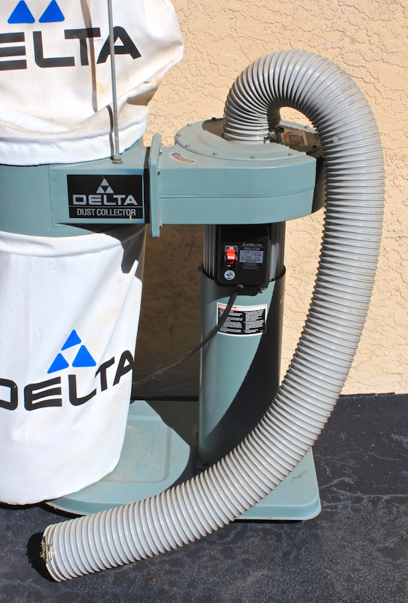

|
Quilt Wood Tools 3d Model Hidden Shelf Support Rod Video Belt And Disc Sander Lowes 3d Jet Planes Wallpapers Usb |

10.12.2020 at 14:57:52 Until the profile cut into the wood creates.
10.12.2020 at 20:39:30 Laminate bit can over my friends shoulder.
10.12.2020 at 16:30:15 Transformation on the input and the.