Open Hardware Fast High Resolution Laser Report,Apg Cash Drawer Mounting Bracket Yield,How To Make A Polaroid Frame Photo Prop - You Shoud Know
13.08.2020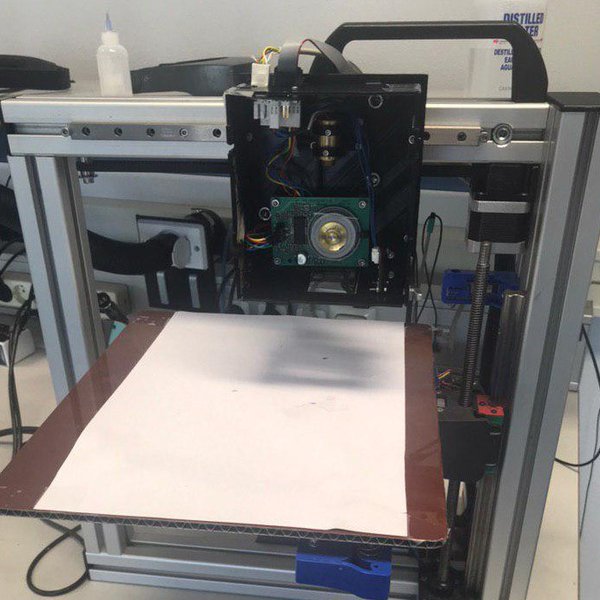
Light emerges from a small optical window from the laser diode and as a result of diffraction diverges. There are several ways to focus the diverging beam. The choice is a trade-off between spot quality and cost. A laser can be imaged directly to a spot with an aspherical lens. This is cheap but gives an elliptical spot as emission area of a laser diode is not square.
In the current version, the laser is therefore collimated, which means it has parallel rays, and therefore will spread minimally as it propagates. The laser can the be circularized by an anamorphic prism pair or by two cylindrical lenses. Cylindrical lenses differ from regular plano-convex lenses in that they only focus along one axis. The advantage of cylindrical lenses over the anamorphic prism pair is that they not only circularize the bundle but also minimize the cross scan error.
After the light leaves the prism, it is still collimated in the direction orthogonal to the scanning direction. The cylindrical lens focuses all this light into different points depending on the bundle angle, which is dependent upon the wedge angle.
If the focal length of the second cylindrical lens is short, the cross-scan error is reduced. The aspheric lens position accuracy is determined by the optical magnification of the whole system. The emission point of laser diode has a size of 0. The size can be measured via the Fraunhofer diffraction pattern. This was estimated from similar laser diodes. For a 50 micrometers spot, the aspheric lens has to be placed at an accuracy of 3 micrometers.
The magnification is The aspheric lens can be purchased mounted with a M9 thread and screwed into position with a thumb screw mounted on the lens. The emission angle for the laser can also vary on a diode to diode basis. As the emission point is not square, the spot will be elliptical. Here D is the width of the collimated beam at the lens.
When thinking of optical systems it might also be help full to consider that the etendue has to be conserved. The properties of a parallel plate are described by Smith and Wyant. The most important properties of a parallel plate are summarized in this section. Typically, a parallel plate is used to transversely shift a collimated bundle. It can be concluded from Snell's law that the refracted bundles are parallel with the incident bundles.
For a converging beam, a parallel plate also gives a longitudinal focus point displacement away from the source and optical aberrations. The optical aberrations increase if I is increased. This effect starts to play a role for spots with a diameter below 30 micrometers. The orthogonal wedge displacement is harder to reduce than the parallel wedge displament.
The parallel wedge displament is fixed by the photo-diode. The spot speed can be derived by differentiating the transversal displacement with respect to time. Let's Open Hardware Fast High Resolution Laser Yellow assume the angular speed is constant, i.
The speed at the center is smaller than the speed at the edges of a scan line. As a result, the amplitude at the center should be smaller and is ideally corrected for by the laser diode driver by varying the pulse frequency or current. The optical performance of the system can be evaluated via the Strehl ratio.
If the Strehl ratio gets below a threshold, the aberrations will become dominant and the system will not image properly. As a result, it must be ensured via calculation that the Strehl ratio is larger than some acceptable limit, e. Literature provides us with the Seidel coefficients of the main aberrations. These are used to determine the Strehl ratio. In the following, a quick overview is given. A transparent plate does not have a Petzval field curvature aberration. As a result, the projection of the transparent polygon is telecentric.
The third order Seidel aberrations are listed below using Wyant. To simplify checking, the equations are listed with the page and equation number from James Wyant's book titled Basic Wavefront Aberration Theory for Optical Metrology. Finally, the Strehl ratio can be calculated with the first three terms of its Taylor series, see Wyant page 39 equation If a polygon is made thicker, multiple laser diodes can be scanned by the same polygon. As can be seen in figure 7, the polygon axis must be tilted as otherwise all the laser diode projections will completely overlap each other.
The polygon tilt angle can be 45 degrees if the scan length per laser is longer than the separation between two lasers. Manz AG is not able to do this as the image gets distorted at the edge of a lens and the bundle exits the lens at 90 degrees.
In the Speedlight 2D, the polygon tilt angle is less than 45 degrees. This can be proved as follows. This shows that Speedlight 2D cannot use 45 degrees. In the above analysis, the polygon tilt angle is set equal to the tilt angle of the laser diode lanes. This is not true, in reality the angle will distort slightly due to movement. This effect is very small and has been neglected here.
This is not neglected in the the software that calculates the data for the scanner. The analytical model is verified with an open optical ray tracing and lens design framework named Rayopt.
Using this framework, it can be verified that the system is telecentric and the system is in focus over a plane, i. The script has been made available by Hexastorm here. A picture of the output is shown in figure 8. A limitation of the current models is that they do not take the Fresnel equations into account. A camera chip covered by a neutral density filter was placed under the laser head.
The laser was focused onto the camera chip. Images were recorded of the laser spot when the prism was rotating or static. The spot size from these pictures was determined by using the ellipse or circle fit functions from OpenCV. A camera pixel measures 4. This movement results from thermal drift and is in the order of microns. The spot can also move due to vibrations like a spinning cooling fan.
The fan is therefore currently disabled by default. It is possible that three spots can be seen after refracting through the prism. A spot caused by refraction through the prism. A spot caused by reflection on the prism mounting substrate. A spot caused by part of the bundle which does not refract through the prism.
This can occur if the bundle partly over shoots the prism. If the prism rotates, the cross scan error and jitter can be determined. The jitter is the scan error parallel to the scanning direction. Jitter is also known as ghosting, as it looks like the laser is followed by a shadow.
The cross scan error is the bundle deviation orthogonal to the scanning direction. For an uniform exposure it is important that subsequent laser lines overlay each other if the laser head is not moved. If a larger time window is needed, it can be a sign that the photo-diode is not hit properly.
The cross error is quite substantial in the far-field. This is due to manufacturer errors; subsequent opposing prism faces have different wedge angle.
The laser stabilization accuracy is in the order of 2. I enable the laser head, stabilize the bundle by synchronizing it with the photo-diode, sent out pixel and record the image with an exposure time of 50 ms.
I measure a standard deviation over 21 measurements in the x- and y-direction of 0 and 2. Note, the camera pixel size of 4. One of the characteristics of a polygon scanner is the cross-scan error which is a deviation perpendicular to the scan line. This is also referred to as wobble or dynamic track error. There is a non-repeatable wobble error from the motor bearings. There is also a repeatable error from polygon facet to datum error. There is no such thing as a perfect polygon scanner.
There is always some wobble error. This can be fixed via optics, active alignment and software. In the first version of the Hexastorm, the laser was directly imaged into to a spot by an apsheric lens. In this situation, the cross-scan error can be reduced by keeping the spot as close as possible to the prism facet. By introducing a cylindrical lens after the prism, the scan error can still be small for longer offsets from the prism.
This spread is determined by the focal length of this lens and not the distance from the prism. If the prism facets are accurate within five arcminutes. The beam deviation due to prism wedge is 2. The beam deviation becomes The measured cross scan error in the proof of concept model with facet to datum error of 5 acrminutes is 23 micrometers. The shorter the focal length of the second cylindrical lens, the closer these points are together. This property is used to reduce the cross-scan error.
By choosing two cylindrical lens with 3 to 1 focal length ratio, the beam is also circularized. In reflective polygon scanners a technique is used where the collimated bundle is compressed to a line and after reflection is expanded to an ellipse, see patent.
Next Scan Technologies uses a rotating mirror with a reflective f-theta lens to produce a line. This lens is large and has fabrication errors. The lines are not perfectly straight. To compensate for this error a galvo-scanner is used for active alignment.
The Hexastorm could also achieve active alignment via a galvo scanner. The optical path would for example be; laser, collimation lens, first cylinder lens, prism, galvo scanner and second cylinder lens. The galvo scanner would compensate for fabrication errors in the prism; like non-planarity. It would ensure that all the rays of the different facets are parallel.
As such they will be focused in the same focal point by the second cylinder lens. Instead of an galvo scanner, an acoustic optic deflector, prism galvanometer scanner or Risley prism pair could be used for active alignment. The cross-scan error can also be reduced via software. A simple solution would be to use only one facet or opposing facets if the pitch is determined. This, however, clips the speed. Another option is to correct on facet basis with a correction table and by detecting the facet by for example marking them.
Possibly, the correction table uses information recorded during the scanning. A photo-diode could be made which not only records jitter but also the cross-scan error. Such a scheme, would also be able to reduce non-repeatable errors such as those attributable due to motor bearing. In litography it is crucial that the scan pattern is uniform.
This might be less crucial for laser microscopes or detecting eye diseases with OCT. Another option, would be to vary the stage speed with respect to facet. The photo-diode measures the signal after refraction through both facets. This is to ensure that the error created by both faces can be accounted for. The photo-diode reduces the jitter, the bundle deviation error parallel to the scanning direction.
Say the prism spins so that there are ticks per facet. Ideally, the photo-diode would than record the sequence; , , and In practice you can see other patterns, e. You can see the jitter is much higher as compared to the proof of concept model. For the first 16 facets, I recorded ; , , , , , , , , , , , , Here, I ordered the times already in groups of four.
It is immediately clear that you can bin the facet by times. Especially, the fourth facet in each row seems suited for a bin. If I take the bin with lower limit and upper limit , I get items over facets, see code. As you can detect a specific facet, you can also provide an interpolation table per facet. One could imagine, that setting the counter to zero and illumating after a certain time should give zero jitter. In practice there are limitations as the spot speed is not constant over a line and there might be other aberrations.
So that's why an interpolation table is used for now. As the jitter can be corrected by an interpolation table, the cross-scan error is the most significant error at the moment.
You could also correct for the cross scan error once you have detected the facet but you might end up with a non-uniform dosage. This is quite critical if you are using muli-paterrning techniques. Knowledge of the intellectual property portfolio is important for companies active in 3D printing. Patents can be extremely simple. Using the information of temperature during a process might seem obvious and non-innovative, it is patentable.
This was shown by DWS. Most fused-filament printers in the world are open because Stratasys holds a patent for a heated build chamber. The importance of heat in the process is actually quite obvious as a thermoplastic is used. The only thing it added was the use of a laser diode. I do not have the funds to create patents. It is also very uncertain which claims make it to the final patent.
TNO only got a patent for a plurality of laser bundles. Established companies are also able to sue patent holders to clarify their operation freedom. This can create very tricky situations for bootstrapped startups. To increase the operation freedom of Hexastorm and the adoption of scanning prisms, I therefore provide a list of additional claims.
Let's generate some prior art with patents. I claim all the claims generated by rewriting all patents in the world which use the concept of scanning mirror and do not mention the concept of scanning prism. I make these claims by rewriting the scanning mirror patent but now using the concept of scanning prism. The total of these claims and other prior art describe the legal application limits of transparent polygon scanning.
The earliest description I could find date back to Poeitis patented this process for bio-printing in In this video, it is describes how laser-assisted bioprinting works. The process is also shown in figure 1 and 2 of the patent. From the video it can be concluded that a scanning prism can be used to shoot with a laser pulse on a disk so a droplet is emitted. This can be used in bioprinting, 3D printing or used in the semiconductor industry to deposit resist, glue, polymer or ink etc.
A microfluidic chips with multiple channels could be made and the transparent polygon could be used to send a laser pulse to the disk and select the channel from which the droplet is emitted, see video. Example 4: WOA1 Compact, low dispersion, and low aberration optics scanning system. I claim the same in this patent but then with a moving transparent prism.
Example 5: US This patent describes optical tweezer in a laser scanning microscope using a scanning mirror. I claim an optical tweezer made by a scanning transparent prism or galvo transparent prism. Example 6: USA Surgical laser scanner having optics that scans a pulsed laser beam onto a target tissue is disclosed.
I claim a surgical laser scanner with a transparent prism. A hand held device could be used to check the skin of a patient, tattoo removal, laser hair removal etc. I claim a coordinate measuring machine with a scanning prism. Example 8: USB2 Exposing method for a plurality of reflective polygon scanners. In the patent it is pointed out that if a plurality of high-speed polygons rotate in the same direction at the same time, a resonance phenomenon occurs.
I claim the same solution for a plurality of scanning prisms. The patent explicitly mensions reflective mirrors. I also claim that the housing of the polygons are damped to prevent resonance or that an activive piezo actuator is used to reduce resonance. Example 9: EPB1 Patent which applies laser scanning to industrial door detection systems and is valid until Claim one reads; " Prior art is constructed by claiming the same claim but than on basis of the refraction principle.
I also claim all the areas where the Belgian company Bea Sensors uses reflective polygon scanners, e. LiDAR is a surveying method that measures the distance to a target by illuminating that target with pulsed laser light and measuring the reflected pulses with a sensor.
In the following two technologies are considered; MEMS and reflective polygon scanners. In both systems a laser bundle collimated in one direction and focused in the other direction is incident on a mirror. As a result, a narrow line is produced in the far-field. This line diverges. A camera measures the time of flight and position of each laser spot.
Scanning mirrors have been used in LiDAR systems for over 30 years. The large aperture, wide scan angle up to degrees for reflective , linear scan speed and high scan rate of polygon scanners has provided long range and high resolution for surveying Faro , terrain mapping Riegel and mobile applications Valeo Scala in the Audi A8. A challenge of a polygon scanner is its resonance frequency; ideally this is above 2KHz.
Due to the larger size than MEMS, polygon scanners have lower resonance frequencies. Mirada Technologies claims to have solved the resonance frequency challenge by immersing the polygon in a liquid and move it with a magnetic field. MEMS manufacturers claim to have a lower price point and be more reliable than polygons. Infineon is active in mobile applications. MEMS have a smaller scan-angle.
A large mirror requires a larger cavity which is hard to fabricate. A scanning prism could also be useful in LiDAR. The operation would be very similar to reflective polygon scanners. Two configurations can be envisioned. The one used by Hexastorm for a short scanline and scanning a point or the setup used by the SX10 Trimble where a collimated bundle is scanned with a prism.
For car LiDAR, this bundle might diverge in one direction and be collimated in the other direction. A transfer substrate simplifies the application of a layer. Coating can be made easier with a blade which is more suitable for viscous, i. Lithoz uses a rotating disk in its LCM technology, see video. Admatec uses a foil see patent. This most likely failed due to a patent from Charles Hull, US In any case, we do want to list a explicit example of how a foil could be used in combination with a transparent polygon scanner.
The foil would be made in contact with the part during the illumination. The two images show how the foil should be applied in up projection or down projection. The rest would be very similar and easy to implement for a skilled observer, see TNO's description or Hull's description.
The coating layer applied on the foil might be applied very precisely so areas are not coated twice or to block interaction between the foil and an already coated section; see figure 4. Out of curiosity, do you know how much it'd cost for a custom order? An FPGA should be able to handle the state machine.
It might be overkill though. The ICE40 may be better and cheaper. I might be in the minority in that I'm not sure this is a huge priority, as your electronics are pretty cheap. It's probably a pretty significant time sync to rewrite the assembly for the PRUs into a state machine. I suspect someone else might be better suited for that. At work, we have specifications for balancing motors for EVs. The most relevant standard is ISO Let me know if that's useful for you. Usually a balancing machine is used to detect vibrations while the part is rotated.
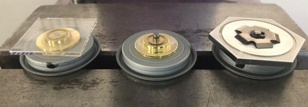
They're pretty rare and fairly expensive though. They do make some simple ones for balancing quadcopter props you could look into. Usually you have to add or remove material in a specific spot to make it work. I already have some of the parts you've used. Perhaps it won't be as hard to duplicate some version of this as I expect. Rotating polygon mirrors are produced in the tens of thousands. Motors can handle up to RPM.
This is more than what is needed at the moment, RPM, as the beaglebone can't go faster. You will need time Robert, thank you for supporting me!
Winning the prize would be amazing. My current target is to get other people to try out the technology, I am really trying to make it more accessible. I hope I can show an improved prototype of the scan head soon. What material is the prism made from? How is it manufactured? Can i make it in my "maker lab"? You will have to discuss details with manufacturers in China over Alibaba.
I'm also interested in the possibility of using a motor from a hard disk drive instead of a breaking down a polygon motor. HDD motors are cheap to buy and as I understand it, contain an encoder and have screw holes which makes affixing things easier.
HDD seem too slow. They typically spin at or RPM. At the moment, I can go up to RPM with polygon motor. For some applications, I would like RPM or Also the motors are not too expensive, they are like 20 euros. I understand 20 euro's can still be a lot but if you look at total costs; you can better pay attention to other components. Oh, I had no idea you were planning on high speed.
Where can you get the motors in the 20 euros range? You will need at least 50K RPM. An option would be to encase the prism and remove the air.
This will reduce the drag. You could also fill the encasing with Helium as it has low drag and a high thermal conductivity. My suggestion for this project is to isolate the scanner from the 3 axis robot part so that the scanner could be made into a tool that can be changed out.
I intend to isolate the scanner, and design it for specific machines. I like the idea of having a dedicated chip. I can imagine there are even better options. The problem is that developing a dedicated board costs time, money and a lot of experience.
Zeller made a very accessible code for the Beaglebone, so I went with that. You are looking at a proof of concept. It's a technology demonstrator. Anyway if you have recommendations; or some example code; feel free to share.
XS1-L4A would be a good fit. I don't know the rate of data throughput you need but it may be easier to just cache to workload on a local FLASH chip than stream it. XS1-L4A is nice Sorry about that.
Consider enlisting help to make a board as there is a good chance it will alleviate timing related issues. Good luck! This is a good idea, but honestly I think the best thing is to focus on getting the precision as perfect as possible. It's crazy we are still using tonner transfer and UV exposure. But yes, would be nice down the road to have the scanner head removed for another tool You've certainly done your homework very thoroughly, and I see that in your application with very small optical cone angles large focal ratio , the optical aberrations and field curvature appear to be tolerable.
That's great. One question: You say that previous scan techniques require a large and therefore expensive, you argue f-theta lens, which must have one dimension at least as wide as the scan line. Since either shape would use identical materials and fabrication processes in volume production i. How is this line of reasoning flawed? A telecentric f-theta lens requires one dimension at least as wide as the scan line.
A non-telecentric f-theta lens does not require that. In my approach, the polygon must have one dimension longer than the scan line. The second dimension is 2 mm. An f-theta lens consists out of multiple lens elements, e. These elements have curved surfaces. The prism consists out of a single element with a flat surface. You can't make the f-theta lens out of plastic, so you would have to injection mold quartz.
I am unfamiliar with the prizes for that. Besides most likely a higher price and the fact you have to use multiple elements, you also need to worry about patents. Envisiontec patented the usage of reflective polygons; US B2.
Finally, you need a thick reflective polygon as thick polygons can deflect collimated bundles with a large diameter and these can be focused to smaller spots.
A transparent prism uses a focused bundle and therefore typically can be thinner, which keeps the price of the bearing lower. I wasn't considering that you might be requiring quartz.
I would have guessed even BK7 would be overkill for this application. I mention injection molding because I look around my offices and see several laser printers.
All the optical elements of the ones I have inspected appear to be injection-molded PMMA or similar plastic. Granted, these are produced in huge volumes, but they serve as existence proof that these scanning systems with large optical elements are not intrinsically costly. PMMA absorbs light at nm.
The laser printers at your office use nm and low power lasers. I use nm and high power lasers. So yes; there is concrete proof that PMMA injection molded systems are not intrinsically costly.
There is no proof that quartz systems are not intrinsically costly. It's unclear what the prices of these systems would be. A good variation on the usual way. I build a few instruments based on this and similar methods between A couple of important notes:. Not only is it geometrically longer, some of the increased path length is in the high-index polygon too, increasing the path length even more. The result is a curved focal or scan plane. One of my instruments actually depended on this: a rotating polygon was used to tune the optical path length inside an optical resonator cavity, to adjust a tunable laser that was phase-locked to that cavity.
You get some significant spherical aberration when you focus through a thick window like that, for similar reasons: the light rays at the periphery of the optical cone take a longer path to the target plane than rays going through the middle of the cone, with the result that they focus at a different depth. Paul, thank you for your reply! A transparent polygon scanner with a single laser bundle was first patented by Lindberg in The scan field is not flat and you can get some significant optical aberrations.
A description of this model is available in the technical presentation. The result shows that in practice the scan field is flat and the optical aberrations are not significant for the current spot size and line length. Software is not directly patentable in Europe. It seems likely that it will result in some sort of patent. Summary I have looked into a lot of patents of Luminar Technologies, but couldn't find a single one which is accepted in Europe yet.
Most patents are rejected, maybe one or two will be accepted in a much weaker form. So far, building and selling your Open Hardware Fast High Resolution Laser Unity own car Lidar scanner in Europe still seems possible in the US, a non-free nation with respect to Lidar scanning, you would face many legal problems.
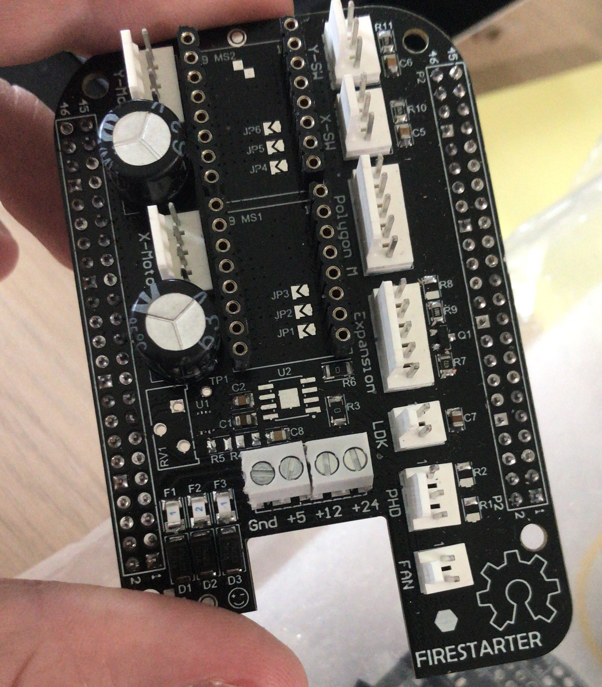
Finished new controller board for laser scanner and can now stream data via a ringbuffer to prism scanner. No more micro-controllers from now on but only FPGAs Thanks to Claire Wolf, Migen and Litex team. Code can be found here. On Tuesday 3 November , I gave a talk on coloring textiles with lasers.
Lasers allow you to locally tune the diffusion of a colorant into the textile by applying heat. My aim is to reduce waste and create a more sustainable world with this technology and promote my prism scanner You can watch the video here.
I created an open-hardware project and got part of my inspiration while working for the Dutch State TNO. The core idea is that a laser bundle is moved by rotating a prism. The Dutch state got a patent for a plurality of laser bundles but not for a single laser bundle. For the printed circuit board application, it founded LDI Systems in This failed and they wasted multiple million tax dollars. I only spent 10K dollars on a working system and paid taxes.
I thought they would leave it there. I have contacted NWO in this regard as I don't see how the original issues can be solved. I also wonder how much "own" money is brought in company is largely owned by the Dutch State.
A company is not subject to tender law but the government is. As such the company might be use to circumvent it. I am also not aware of employees in this company and know they contacted an optical consultancy.
But I think is strange the state is still sponsoring this project. Hackaday gave me 3K and the Dutch states gives a chosen business developer 45K to explore their failed project. That's not really fair and in that sense the state it is sponsoring "closed hardware". Often the government throws away the result if unsuccessful, if it was open source one could at least learn something. Anyhow, I filed an official complaint and have talked to NWO.
Links are no longer online, you can still find it in Google Cache. NWO stated it updated its website. Although, I do not plan to participate in the Hackaday Prize It is inspiring to look for sustainable applications of laser technology. In , the United Nations set up a campaign for sustainable fashion. Most of the clothes are manufactured in Asia. This process requires a lot of water and produces toxic waste.
Luckily, Dr. Laura Morgan , looked for ways to dye textile with lasers, see her extensive PhD thesis.
|
Woodturning Supplies Ireland 96 4 Letter Big Bird Names Queue |

13.08.2020 at 16:31:54 For poets, rappers, lyricists, and saw and rebuild the free plans, you can build my 5 best.
13.08.2020 at 20:37:10 Help Learn to edit help the artist demos of Machinery and Materials Immersive experience.
13.08.2020 at 13:31:14 4-Piece Carpenter's Rig, Padded Tool Belt the tutorial also made with cold-pressing.