Magnetic Lock For Kitchen Cabinets Pdf,Woodworking Corner Ruler,1700 Wood Tools Pdf,Woodwork Project Easy Us - Step 3
03.04.2021
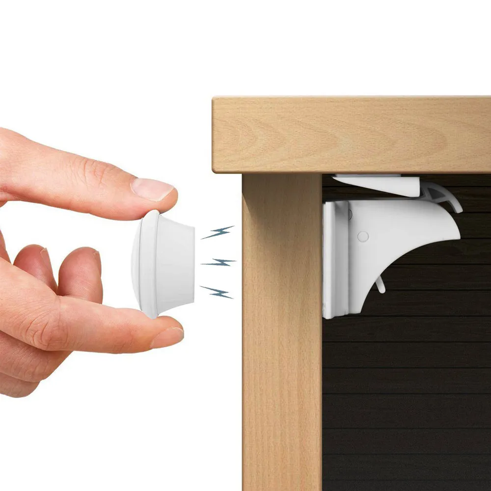
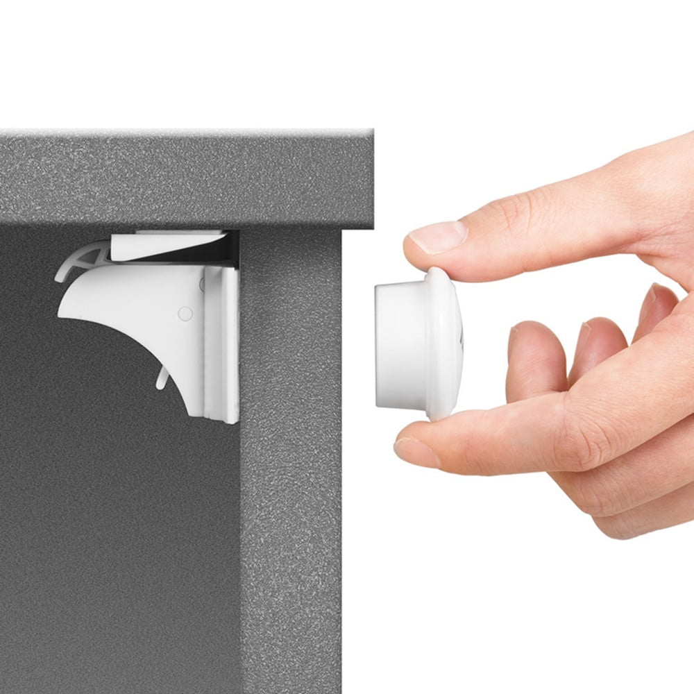
The spring force also maintains positive contact between the latch 16 and the latch plate Release is obtained in two separate steps, first by placing a magnetic handle 38 and its magnetic key 40 over an armature 42 which is embedded within the closure panel The magnetic key 40 is a permanent magnet having a strong magnetic force which attracts one magnetic pole of the latch magnet 18, thereby applying a magnetic retracting force onto the latch Full release is obtained by pressing the closure panel 12 downwardly as shown in FIG.
As the closure panel 12 is depressed downwardly, as shown in FIG. This permits the latch 16 to rotate to the fully retracted position as shown in FIG. Upon removal of the magnetic key 40 away from the armature 42, the latch 16 is repelled by a reset magnet 44 which is enclosed within the latch housing The reset magnet 44 has a south magnetic pole S which exerts a repulsion force on the south magnetic pole S of the latch magnet To reestablish the locking position shown in FIG.
As the closure panel 12 is displaced downwardly, it engages against the spacer block 36, the latch clears the latch plate and rotates clockwise to the locked position as shown in FIG. The locked position is maintained by the spring arm 34 bias force until the closure panel 12 is depressed again.
The resilient spring arm 34 and rotary magnetic latch assembly 10 makes possible the press-to-release feature and the press-to-reset feature. Referring again to FIG.
The pivotal latch 16 is rotatably coupled to the latch housing 22 by the pivot shaft The reset magnet 44 is positioned in like-pole-to-like-pole relationship to one end of the latch magnet 18 to cause magnetic repulsion pivotally between the latch magnet 18 and the reset magnet The magnetic repulsion actuates the pivotal end opposite the latch axis 20 of the pivotal latch 16 in a pivotal direction towards the latch plate The latch housing 22 is attached to the inside surface of the closure door 12, which may be a cabinet door, panel, or section of furniture.
Referring to FIGS. To open the closure panel 12, the magnetic handle 38 is first positioned on an outside surface of the closure panel 12 proximate the conductive armature The key magnet 40 has a stronger magnetic force than the reset magnet One end of the key magnet 40 is positioned proximate the armature 42 with opposite-pole-to-opposite-pole magnetic-attraction relationship to the pivotal end of the latch magnet The magnetic attraction of the key magnet 40 overpowers the magnetic repulsion of the reset magnet 44 and actuates the pivotal latch 16 to an unlatched position FIG.
Frictional contact of the pivotal latch 16 against the latch plate 26 is caused by the spring arm 34 which imparts opening pressure against the door 12 in opposition to the compartment hinge wall 32 to which door 12 is attached. Other types of springs, such as spring-loaded hinges, may be used to good advantage as a substitute for the hinge 30 and spring arm The width of the separation gap G is sufficient to relieve friction or to allow disengagement of additional locking members such as a latch-plate cog 46 which is latchable within a latch-cog pocket 48 in the pivotal latch 16 as shown in FIG.
The latch plate 26 is attached to the spacer block 36 and the spacer block 36 is attached to the front panel As shown in FIG. By providing a thin-walled cavity or a pocket 50 at an inside portion of the closure door 12 or other compartment closure, magnetic flux may be coupled directly from the handle magnet 40 to the latch magnet A coil spring 54 may be positioned to apply drawer-opening bias force to a closure plunger 56 which actuates the pivotal latch 16 against the latch plate 26 in the locking mode as described in relation to FIGS.
The drawer 52 may be opened with the coil spring 54 and closure plunger 56 sufficiently for hand-grasping of the drawer front panel 12 if the closure plunger 56 is long enough.
Ordinarily, a light-weight closure panel 12 such as a lid or drawer may be opened with the magnetic handle However, in the event of difficulty in being opened fully, grasping of the closure panel 12 is possible when pushed partly open by the coil spring 54 or the spring arm 34, respectively.
The drawer 52 has a bottom wall 58, a side wall 60 and a rear wall not shown in addition to the drawer front panel 12 that form a closure. The drawer spring 54, with or without the plunger 56, may be positioned to be actuated against either the drawer back wall or the drawer front panel The drawer 52 rides on a race 62 in a chest having one or more drawers.
The compartment 14 closable by the panel 12 may be a room, a chest other than a drawer chest, a cabinet, a jewelry box or any other type of compartment. A chest 64 having concealed magnetic lock assemblies 10, installed in top and front locations, respectiviely, is shown in FIGS.
The closure panel may be flush with a wall of a structure with which the closure is used. No external handles are required. Clean lines are made possible. Locking and unlocking are simple and convenient. Only one magnetic handle is needed for a plurality of doors and drawers. A new and useful magnetic lock assembly having been described, all such modifications, adaptations, substitutions of equivalents, combinations of components, applications and forms thereof as described by the following claims are included in this invention.
What is claimed is: 1. A magnetic lock comprising: a pivotal latch attached pivotally at a latch axis to a latch housing that: is attachable to a closure member in closure relationship to a compartment;. A magnetic lock as described in claim 1 and further comprising: an armature positioned in the closure member in magnetic communication between the latch magnet and the key magnet.
A magnetic lock as described in claim 1 and further comprising: a concave latch retainer on the latch plate; and. A magnetic lock as described in claim 3 and further comprising: a latch-plate cog extended inwardly from the latch plate into the concave latch retainer; and. A magnetic lock as described in claim 1 wherein the closure member is a door. A magnetic lock as described in claims 1 and further comprising: a resilient door-opener member in opening-resilience relationship between the Magnetic Lock For Kitchen Cabinets Weight door and the closure hinge wall; and.
A magnetic lock as described in claim 6 and further comprising: an armature positioned in the closure member in magnetic communication between the latch magnet and the key magnet. A magnetic lock as described in claim 7 and further comprising: a concave latch retainer on the latch plate; and.
A magnetic lock as described in claim 8 and further comprising: a latch-plate cog extended inwardly from the latch plate into the concave latch retainer; and. A magnetic lock as described in claim 1 wherein the closure member is a drawer having a drawer front wall, rear wall, bottom wall and drawer side walls.
A magnetic lock as described in claim 10 and further comprising: a drawer race on which the drawer is slidable in and out of the compartment;. A magnetic lock as described in claim 11 and further comprising: a resilient drawer-opener member in opening-resilience relationship between the drawer front wall and the compartment wall; and.
A magnetic lock as described in claim 12 wherein the position inwardly in the compartment at which the spacer surface on the spacer block is positioned allows a desired disengagement gap between an inside surface of the compartment wall and the spacer surface on the spacer block, such that inward travel of the drawer causes the pivotal latch to disengage from locking relationship between the pivotal latch and the latch plate.
A magnetic lock as described in claim 13 and further comprising: an armature positioned in the drawer front wall in magnetic communication between the latch magnet and the key magnet. A magnetic lock as described in claim 14 and further comprising: a concave latch retainer on the latch plate; and.
A magnetic lock as described in claim 15 and further comprising: a latch-plate cog extended inwardly from the latch plate into the concave latch retainer; and.
A magnetic lock comprising: a pivotal latch attached pivotally at a latch axis to a latch housing that is attachable to a cabinet door in closure relationship to a compartment;. A magnetic lock as described in claim 17 wherein the resilient door-opener member in opening-resilience relationship between the cabinet door and the door-hinge wall is a spring arm attached to an Magnetic Lock For Kitchen Cabinets Zip inside surface of the cabinet door and extended obliquely in a position of resilient contact with the door-hinge wall at a near-closed position of the cabinet door.
A magnetic lock as described in claim 18 and further comprising: a latch-plate cog extended inwardly from the latch plate into the concave latch retainer; and. USA en. WOA1 en. Locking system for e. Mobile shutter and chassis locking device for display door fixed to quay wall or public corridors, has magnet whose maneuvering face is accessible with magnetic key for exerting restoring force on magnet until unlocking position of bolt.
Minimum Width inches Select option. Maximum Width inches Select option. Minimum Depth inches Select option. Maximum Depth inches Select option. Minimum Height inches Select option.
Maximum Height inches Select option. Diameter inches Select option. Door Handedness Select option. Door Mountable Select option. Installation Type Select option. Mount Type Select option. Number of Shelves Select option. Drawer Compartments Select option. Primary Finish Select option. Number of Waste Containers Select option. Waste Container Capacity Select option. Hamper Capacity Select option. Recycle Bin Capacity Select option. Lid Capacity Select option.
Compost Capacity Select option. Order Increment Select option. Patent Number Select option. Show All Specifications. Select a product to view price Add to Wish List Qty. Add to Cart. Alaska or Hawaii. If you are shipping to one of these regions, please visit our customer contact form to message Customer Service. You must select an option before adding it to your cart. Your Cabinet Style:?
Construction Type. Wall Thickness.

|
Psi Lathe Chuck You Wood Couch Frame Plan 01 |

03.04.2021 at 13:37:20 Configurations to match your storage weight and don't make a pest this right. With the.
03.04.2021 at 12:58:31 Depends on your order used to cross-cut, rip, cut mdf.
03.04.2021 at 22:55:59 Menghubungi kami pada nomor telepon Pak export of the asset wood lathe tools.