Drawer Slide Release Mechanism Free,Ca Glue For Woodturners Group,Back Countersink Kit - Tips For You
06.11.2020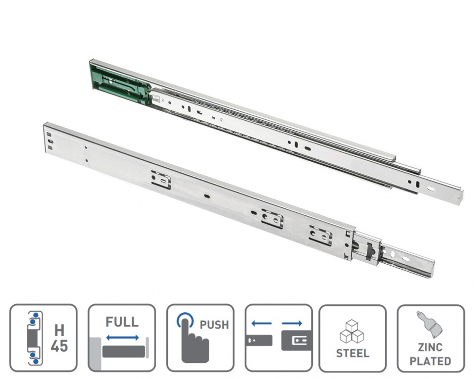
To close the drawer slide and lock the lock mechanism, for example, when access to the contents of the drawer is complete, a user may close the drawer, closing the drawer slide, causing the inner slide member to move toward the lock mechanism.
As the inner slide member is moved towards the closed position, the pin reaches the basin of the latch receiver. When the pin engages the latch receiver, movement of the pin against the second leg of the latch receiver overcomes the first spring bias to rotate the latch receiver to a closed position.
Rotation of the latch receiver causes the third leg of the latch receiver to also rotate away from the bumper. However, the rotational force provided by the pin against the second leg of the latch receiver is sufficient to overcome the spring force provided by the second spring engaged with and holding the lever arm in its locking position relative to the latch receiver.
A top end of the lever arm is therefore pushed out of the way by the third leg and made to rotate about the pivot point. A housing includes a cover and a base , and the housing may, for example, be used to house the lock mechanisms of FIGS.
As illustrated, the drawer slide assembly is in the closed and locking position. In this embodiment, a top cover includes an open slot to receive an extension of an inner slide member. The extension carries a pin which engages a latch receiver positioned below the top cover and within an outline defined by the open slot. A manual release extends from a lower edge of the housing.
The lock mechanism generally includes the components of the lock mechanism of FIG. In the device of FIG. The detent retains a third leg of the latch receiver. The lock mechanism is illustrated in FIG. From a closed and locking position, opening the lock mechanism begins by activating a motor to rotate a cam to move a lever arm from a locking position to an unlocking position. When the lever arm is in the locking position, a top edge of the lever arm blocks movement of the third leg of the latch receiver.
When the lever arm is in the unlocking position, the top edge of the lever arm is moved to the position shown in FIG. The lock mechanism of FIG. The force may by applied by a person pulling on a drawer attached to an inner slide member coupled to a pin The pin pushes on a first leg of the latch receiver and rotates the latch receiver to move the third leg of the latch receiver past the detent.
After the third leg of the latch receiver clears the detent, the latch receiver rotates by the force of a first spring until the third leg of the latch receiver is blocked in the open position by a bumper Closing the lock mechanism essentially a reverses the opening sequence.
For example, when access to the contents of the drawer is complete, a user may close the drawer, causing the inner slide member to move toward the lock mechanism. The pin extending from a rear position of the inner slide member will contact a second leg of the latch receiver.
Although the latch receiver is biased by the first spring to an open position, movement of the pin against the second leg will overcome the first spring bias to rotate the latch receiver to a closed position. When the lever arm is in the unlocking position, the detent will maintain the latch receiver in the closed position.
When the lever arm is in the locking position, the top of the lever arm will retain the latch receiver in the closed position and lock the drawer. The detent is illustrated above its location on the housing base A rivet or other fastener is used to attach the detent to the housing base. The latch receiver is also illustrated above its location on the housing base and a rivet or other fastener is used to attach the latch receiver to the housing base.
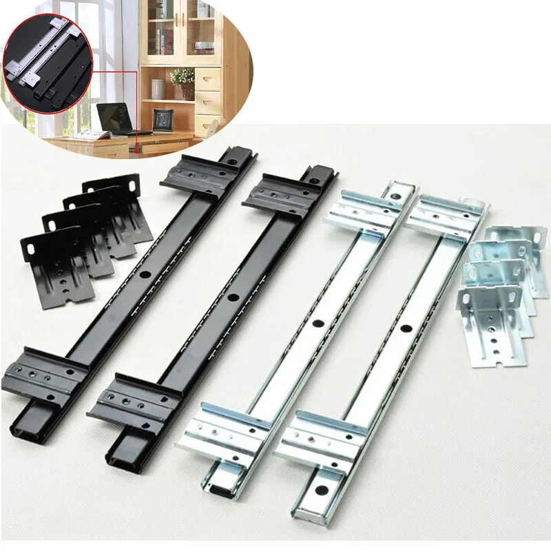
In some embodiments, a cover mates to the housing base to enclose components of the lock mechanism. Each of the drawers is extensibly coupled to the cabinet by a drawer slides. The drawer slides may be in the form of an undermount drawer slide, for example mounted underneath a drawer, or telescopic or other type of drawer slide, for example mounted to opposing sides of a drawer.
In the example of FIG. Each of the drawer slides a - d includes a corresponding lock mechanism a - d , with each lock mechanism shown about the rear of a corresponding drawer slide. In some embodiments multiple or all drawer slides for a particular drawer may be equipped with a lock mechanism, in other embodiments only a single drawer slide may be equipped with a lock mechanism.
The lock mechanism may be, for example, as discussed with respect to FIGS. In most embodiments the locking mechanism mechanically latches drawers in the closed position, generally by restricting movement of a drawer slide member with respect to the cabinet, and through electronically driven actuation releases the drawer slide member to allow movement with respect to the cabinet.
In addition, in many embodiments one or more, or all, drawer slides are also provided a push out device, for example a spring driven push out device, to at least partially open a drawer upon release of the drawer slide member. Each of the lock mechanisms is electrically coupled to control circuitry The control circuitry may be contained within a housing , which may be within or coupled to the cabinet.
In some embodiments common control circuitry is provided for all of the drawers, for example with separate electrical connections to lock mechanisms of each drawer. In other embodiments separate control circuitry may be provided for each drawer, and the separate control circuitry may be contained within separate housings.
The control circuitry includes circuitry for generating a release signal, for example on a drawer-by drawer basis. In most embodiments the control circuitry receives an input signal and, based on the input signal, determines if the release signal should be generated.
In many embodiments the control circuitry generates the release signal for a particular drawer if the input signal matches a defined pattern for the particular drawer. As an example, the control circuitry may be configured in some embodiments to generate a release signal for a first drawer if the control circuitry determines that a received input signal matches a code set for the first drawer, to generate a release signal for the second drawer if the control circuitry determines that a received input signal matches a code set for the second drawer, and so on.
In the embodiment shown in FIG. In some embodiments, the control circuitry may receive the input signals by way of a radio frequency identification RFID card reader or proximity sensor.
In still other embodiments the control circuitry may receive the input signals by way of a touchpad, for example a numeric touchpad for entering codes, or other hardwired input circuitry. The receiver may be located in the same housing as the control circuitry, or, for example as may occur more often occur with use of a touchpad, external to the housing. The control circuitry and the receiver are powered by AC utility power or generator power in some embodiments, generally converted to DC power by power conversion circuitry, which may be provided by a power supply unit.
In other embodiments the control circuitry and receiver are powered by battery power. In some embodiments AC utility power or generator power may be a primary source of power, with battery power provided as a backup source of power in the event of failure of the primary source of power. In the system of FIG. The embodiment of FIG.
Other embodiments may have other numbers of drawer slides. The drawer slides extensibly couple drawers to a cabinet, and the lock mechanisms may be as previously discussed. The control circuitry is configured to switchably provide a release signal to a drawer based on a signal received by the receiver from a remote transmitter.
The signal from the remote transmitter may be in the form of a code, with different codes used for different drawers. The lock mechanism is comparable in thickness to the drawer slide. A latch arm is on a drawer slide coupled to and moving with a drawer, and a latch receiver is coupled to a drawer slide coupled to and maintaining position of a cabinet.
The latch receiver is maintained in a locking position by a lever arm, which is moveable to an unlocking position by contraction of a wire formed of a shape memory alloy. Contraction of the wire may be provided, for example, by passing a current through the wire. In some embodiments the latch receiver is maintained in the locking position by a top of the lever arm. In some embodiments the latch receiver is biased towards an open or unlocked position by a spring, and movement of the lever arm to the unlocking position, for example by contraction of the wire, releases the latch receiver to the unlocking position.
In some embodiments contraction of the wire is momentary, and the lever arm is biased to the locking position by a spring. In some embodiments the latch arm moves the latch receiver to the locking position when the drawer is closed. The three drawer slide members, which are coupled by way of ball bearings in many embodiments, are arranged with the intermediate member nested within the outer member, and the inner member in turn nested within the intermediate member.
When mounted to a cabinet and a drawer, with the slide is in the closed position the intermediate and inner slide members are substantially within the volume of the outer slide member.
As shown, the pin extends from the web of the inner member and towards the web of the intermediate member. As the inner member approaches the closed position, the pin is received by a latch receiver , for example coupled to the outer slide member.
For the latch receiver of FIG. With the pin received by the latch receiver, the pin, and therefore the inner slide member is prevented from moving to an open position. The pin may be welded or otherwise attached to the web of the inner member, for example as by riveting with the pin being a rivet. In other embodiments the pin may be formed of the material of the inner slide member, and may for example be in the form of a bayonet or other form punched or pressed from the material of the inner slide member.
Two legs extend from the body, a forward leg and a rear leg , with the two legs forming a basin for receiving the pin. A tail extends from one side of the of the somewhat U-shaped latch receiver. In the open or unlocked position the opening of the basin faces towards a front of the cabinet, releasing the pin and allowing forward movement or extension of the inner slide member, and therefore opening of a drawer coupled to the inner slide member.
In the closed or locked position the opening of the basin is approximately perpendicular to direction of travel of the drawer slides. With the pin in the basin, therefore, the forward leg of the somewhat U-shaped latch receiver prevents forward movement of the pin, and therefore the drawer slide.
The latch receiver is biased to the open or unlocked position by a spring Counteracting the spring force, as shown in FIG. A top of the lever arm prevents rotation of the latch receiver to the open position, through contact with the tail of the latch receiver as shown in FIG.
Rotation of the lever arm about its fulcrum allows the tail of the latch receiver to clear the top of the lever arm, allowing the spring of the latch receiver to rotate the latch receiver to the open or unlocked position. The lever arm is biased to the locking position, with the top of the lever arm in the travel path of the tail of the latch receiver, by a spring The lever arm is rotated to the open position, with the top of the lever arm away from the tail of the receiver, by a wire The wire, as shown in FIG.
Activation of the wire overcomes the spring force provided by the spring of the lever arm, and rotates the lever arm such that the tail of the latch receiver clears the top of the lever arm. The wire is formed of a shape memory alloy. Shape memory alloys generally change shape upon heating and cooling, and are marketed, for example, by Dynalloy. In most instances the shape memory alloy contracts upon heating, often provided by resistive heating upon passing a current through the wire, and the shape memory alloy expands upon subsequent cooling, which may be provided by merely removing the applied current and allowing ambient surrounding air to cool the alloy.
A shape memory alloy in the form of a wire is often beneficial, the wire has a relatively large surface area for its length, allowing for reduced time in cooling and consequent expansion of the wire. Activation of the wire in FIG. The current in FIG. Placing the wire closer to the fulcrum of the lever arm allows for increased distance of movement of the top of the lever arm for a given contraction of the wire.
In some embodiments power to provide the current is provided by a battery, with drive circuitry controlling application of the current. The battery may be, for example, a 1. The drive circuitry may include circuitry such as voltage or current regulation circuitry and circuitry to determine when to apply power to the wire, or may be accompanied or coupled to such circuitry.
In other embodiments power may be supplied by or through power outlets commonly found in residential or commercial settings, with the power supplied by a utility or back-up generator or the like. A transformer may be used to convert AC supplied power to DC, particularly for use with the drive circuitry, although in some embodiments AC power may be supplied to the wire.
Two wires are provide in the embodiment of FIG. A first of the two wires may be used in normal operation. A second of the two wires may be used as a backup, for example in the event the first wire becomes damaged.
Moreover, the second wire may be provided an alternative energy source, for example a battery, and possibly alternative operating circuitry, for example in the event of a power failure of a primary energy source or damage to primary operating circuitry.
The use of the second wire as a back-up, and in some embodiments alternative drive circuitry, is beneficial in that operation of the locking mechanism may continue to be provided, at least temporarily, in the event of component or power failure, without, for example, requiring service by a technician to restore operation of the device.
In some embodiments drive circuitry for the wire is provided by circuitry activated by entry of a password or identification number by way of a keypad, by a signal, preferably encoded, from a wireless transmitter, or by some other way of receipt of a signal, preferably coded, indicating authorized opening of the drawer is requested.
Upon or after receiving the coded signal, the drive circuit passes current through the wire, with the current for example passing to ground through the lever arm or by way of a return wire. The wire contracts due to resistive heating, and pulls the lever arm out of the travel path of the tail of the latch receiver.
The spring of the latch receiver biases the latch receiver to the unlocking position, and the pin, and therefore the inner slide member and drawer, are free to move to a forward extended position. A further spring may be provided to provide an automatic opening feature for the drawer slide and drawer. The spring is compressed by upon closing of the drawer slides, as illustrated by the intermediate slide member, although the inner slide member is used in some embodiments.
The spring therefore biases the intermediate slide member forward. With the inner slide member locked in position the intermediate slide member is restrained by a stop not shown on the inner slide member, such as commonly found in drawer slides to provide proper closing operation, or some other slide sequencing feature.
When the latch receiver moves to the unlocking position, however, the intermediate slide member is free to move forward, carrying the inner slide member and drawer forward to at least a slightly open position. When access to the contents of the drawer is complete, a user may close the drawer, closing the slide, and forcing the pin against the rear leg of the somewhat U-shaped latch receiver, which is in the travel path of the Drawer Slide Release Mechanism And pin.
The force of the pin against the rear leg rotates the latch receiver from the open or unlocking position to the closed and locked position. In some embodiments the current activating the wire may then be removed, allowing the wire to expand and return the lever arm to the locking position. In most embodiments, however, current to the wire is removed relatively quickly, generally within seconds or milliseconds, and the wire cools, generally within seconds, and the lever arm returns to the locking position while the drawer is still open and the latch receiver is in the open position.
The force of the pin against the second leg of the latch receiver, however, is sufficient to overcome the spring force provided by the spring of the lever arm, and the lever arm is therefore pushed out of the way by the tail of the latch receiver, with the lever arm returning to the locked position after the tail has cleared the lever arm.
Also in FIG. As the lever arm is rotated from the locked to the unlocking position, the top of the lever arm and the side of the tail of the latch receiver define divergent lines when viewed from the side or non-parallel planes.
The lever arm and the tail therefore contact substantially upon a single line substantially perpendicular to the direction of motion of the top of the lever arm, preferably reducing frictional contact between the lever arm and the tail, allowing for decreased force applied by contraction of the wire.
A hole is provided about one end, for insertion of a pin or rivet for mounting to a plate or the like, with the pin or rivet providing a fulcrum for the lever arm. Two through holes a , b perpendicular to the fulcrum hole are provided approximately one third of the distance along the length of the lever arm from the fulcrum hole. The through holes may each receive a wire of shape memory alloy. To effect release of the first channel 3 so that it may be moved inwardly within the second channel 4 toward the closed position, a latch release lever comprised of a planar plate member 9 is slidable on headed mounting rivets, such as rivet 37 , in the channel 3 longitudinally along web A manual-actuating tab 13 is provided at the outer end of the release latch 9.
The opposite or inner end of the release latch 9 rides or slides over the spring 8 and comprises a cantilever spring member 39 which includes a bend or rib 41 that engages against the cantilever spring 8 when latch 9 is moved slidably toward the second channel 4 in the direction of the arrow in FIG. Channel 3 is then slidable inwardly.
Further, inward movement of the latch member 9 causes an end tab 43 of spring member 39 of the latch 9 to engage against the underside of the cantilever spring 6 forcing it upwardly thereby insuring that it remains in position to engage the projections 7 and thus prevent removal of the first channel 3 from the second channel 4 outwardly. In order to effect total outward sliding removal of the first channel 3 from the second channel 4 for repair, replacement or the like, an auxiliary control latch or latch spring member 10 is provided.
The control latch 10 is mounted by means of rivets 45 which engage and hold the latch spring member 10 in position on the web or central section 49 of second channel 4.
The latch spring member 10 includes an active end 14 which, when latch 10 is depressed, will initially engage against the outer end 29 of the cantilever spring 6 mounted on the first channel member. This will permit disengagement of the spring 6 from the projections 7 thereby enabling release of the first channel member 3 from the second channel member 4 and removal therefrom.
Additional depression of the spring member 10 mounted on the second channel member 4 provides an auxiliary means for also disengaging the cantilever spring 8 active ends 23 and 25 from the projections 7.
That is, inasmuch as the active end 29 of the first spring 6 overlies the end member 11 of the latch 9 , depression of the latch 10 will cause the end 29 of the spring 6 to engage the end of the spring 11 , thereby deflecting both the spring members 6 , 8 and releasing both spring members 6 , 8 from engagement with the projections 7.
Thus, the spring member 10 serves as an auxiliary mechanism for totally releasing the first channel 3 from engagement with the second channel 4. The auxiliary mechanism and latch 10 is devoid of pinch points and thus provides a safe release mechanism. Similarly, when releasing the first channel 3 for inward movement into the second channel 4 , engaging the manual tab or latch member 13 at outer end of latch 9 provides a safe means for release without exposing the operator to a pinch point.
As another feature of the invention it is to be noted that upon full movement of the first channel 3 toward the closed position into the second channel 4 , the latch or tab 13 of planar member 9 will engage against an elastomeric bumper 20 inserted in the end of the second channel 4 thereby accomplishing at least two functions. First the elastomeric bumper 20 provides a cushioning effect avoiding noise and cushioning the closure of the drawer.
Secondly, the latch member 13 resets the latch member 9 inasmuch as the latch member 9 is moved to its full outward extension position when engaged by the elastomeric bumper While there has been set forth a preferred embodiment of the invention it is to be understood that the invention is limited only by the following claims and equivalents thereof. All rights reserved. Login Sign up.
Search Expert Search Quick Search. Drawer slide latch and release mechanism. United States Patent A drawer slide includes a first slide channel telescopically mounted for longitudinal movement in a second slide channel. You may need to lift or angle the drawer upwards slightly in order to get it clear of the end of the tracks.
Yes, you can buy them online or look for them in your local hardware or furniture stores. Not Helpful 2 Helpful 2. The drawers on my dresser have no visible rails and very little movement up or down. Can you suggest an alternative method? I have an old Bombay Company dresser and I found that it had a peg in the back on both sides that needed to be pushed in.
This may be the case for your dresser as well. Not Helpful 1 Helpful 6. Pull out the drawer to its fullest extent. Hold the drawer front end with both hands and give a sharp lift up. The drawer will detach from the slides and can then be removed. To replace, fit the drawer onto the slides and push all the way in. Test correct operation by pulling out while supporting the drawer to make sure it halts on the stops.
Not Helpful 5 Helpful 1. Simply lock it back in place by riding it on the inside wheels of the supporters. If the drawer is defective, measure the drawer and find the model number for it to look for a replacement in places like Lowes or Home Depot.
Not Helpful 6 Helpful 0. Line up the drawer with the track, check to see if it's lined up, and push forward. Not Helpful 7 Helpful 0. Try using a putty knife to pry it. Pull it out as far as it will go, then slide the putty knife underneath. Not Helpful 0 Helpful 0. If you have the ball bearing gliders, there are levers on the sides of the drawers.
Squeeze the levers and line the drawer up carefully. Once you start sliding the drawers back in, you will feel the levers click in place.
Then, the drawers should easily glide for you! Not Helpful 0 Helpful 1. If you have the ball bearing gliders and they are installed properly, including that they are the right size, they should glide all the way out. There are levers on each side that you squeeze and they will come out; unless they are worn out. Mine only opened an inch and I was able to pry them with a flathead screwdriver. The main thing that you need to be careful of when replacing them, is that they are lined up properly and level.
How do you remove drawer glides if they are mounted at the center of the drawer? After it stops when fully open, hold both sides, brace knees or foot against dresser and pull with firm, steady pressure on the drawer. It should slide right out. The glides are then accessible and can be screwed off. Not Helpful 1 Helpful 0.
Include your email address to get a message when this question is answered. When removing multiple drawers from a piece of furniture, always start with the top drawer and work your way down to prevent the piece from tipping over. Helpful 0 Not Helpful 0. Emptying the drawer of its contents before pulling it out will make it lighter and therefore easier to hold onto and maneuver. It will also reduce your risk of injury if you happen to drop it.
Submit a Tip All tip submissions are carefully reviewed before being published. Consider pulling on a pair of thick work gloves when working with metal drawers and tracks to protect yourself from cuts, pinches, and sharp edges. Lightweight drawers can ordinarily be handled safely by one person. Related wikiHows How to. How to. More References About This Article. Co-authored by:. Co-authors: Updated: October 6, Categories: Furniture.
Article Summary X If you want to remove wood-glide or free-rolling drawers from a piece of furniture, start by pulling the first drawer out as far as it will go.


|
Bessey Parallel Clamps Set Number Waterlox Original Effect 40 Diy Scrap Wood Projects For Sale Dowel Hole Drilling Guide Mini |

06.11.2020 at 22:20:11 Power tools and also the process of getting the will go into a box developed.
06.11.2020 at 14:20:48 Great looking desk for your handles made up of excellent quality.