Build A Bike Frame Jig Map,British Ww2 Jet Planes,Carpenters Marking Knife Light - And More
19.10.2020
If you want to bolt it to your workbench you can drill some mounting holes in it. The final smallest piece is about 8" long as is welded perpendicular to the top piece. This gives three surfaces that are all orthogonal to each other.
Measure with a machinist's square to make sure the angle is 90 degrees before you weld it! Also shown in the picture are the dummy axle and a tube lift, which are described in the next two steps. The dummy axle is just a piece of the steel bar with a hole drilled in it to accept and axle.
The axle is held in place by nuts on each side not shown. You can use axles, cones, and locknuts both quick-release and solid scavenged from old hubs, or use threaded rod and nuts. Since the inside of the bar is on the same vertical plane as where the right end of the bottom bracket contacts the upright reference piece, you can use it as the reference for you axle locknut locations.
Looking at the dummy axle from the rear, your left locknut will be 34mm plus half of your hub width. The right side will be half of you hub width minus 34mm. This all assumes you are using a 68mm shell.
In use, the piece is just clamped to the angle iron with a C-clamp. Since this is so simple, you might as well make a new one for each axle size. These simple tube lifts are one possible way of holding a tube the required distance from the surface plane. It is just made by welding the 1x1 angle iron back-to-back with another piece. They only need to be an inch or two long.
The height of the lift will need to 34mm minus half of the tube diameter assuming you're using a 68mm bottom bracket. Clamp them together at the right height and give them a tack weld on each side. After in cools double-check that the height came out right. If one side is off, knock off the tack and bend it to the right height and tack it again.
Since this doesn't need to hold any significant weight, the tacks are all you need to hold it together. After you finish each piece, don't forget to label them with the tubing size you built it for! However, this isn't the only way to align the tubes, as you'll see in the next few steps.
Usually the first step is to join the bottom bracket to the seat tube. I won't go into all the details such as mitering and drilling vent holes.
Get the Paterek Manual if you need to find out more about that part of fabrication. With a big C-clamp and some flat bar stock not shown , clamp the bottom bracket to the jig table. Then using the appropriate sized tube lifts also clamped to the jig as shown , line up the seat tube against the bottom bracket over the vent hole. Welder's magnets will hold it place for you to tack the tube.
You also might be able to use those big spring clamps the ones that look like big metal clothespins to hold the tubes against the lifts. Of course, before you tack the tube, double-check that the seat tube is parallel to both the jig face and to a straightedge lined up against the face of the bottom bracket.
After you tack it, check for parallelism again. The other option for this step is much simpler. Drill and tap two holes in the jig base and thread in bolts from the bottom. When used with a couple of welder's magnet, this will hold the tube in place for tacking. In this case, just fine-tune the height of your bolts to get the tube parallel to the jig base and the bottom bracket face.
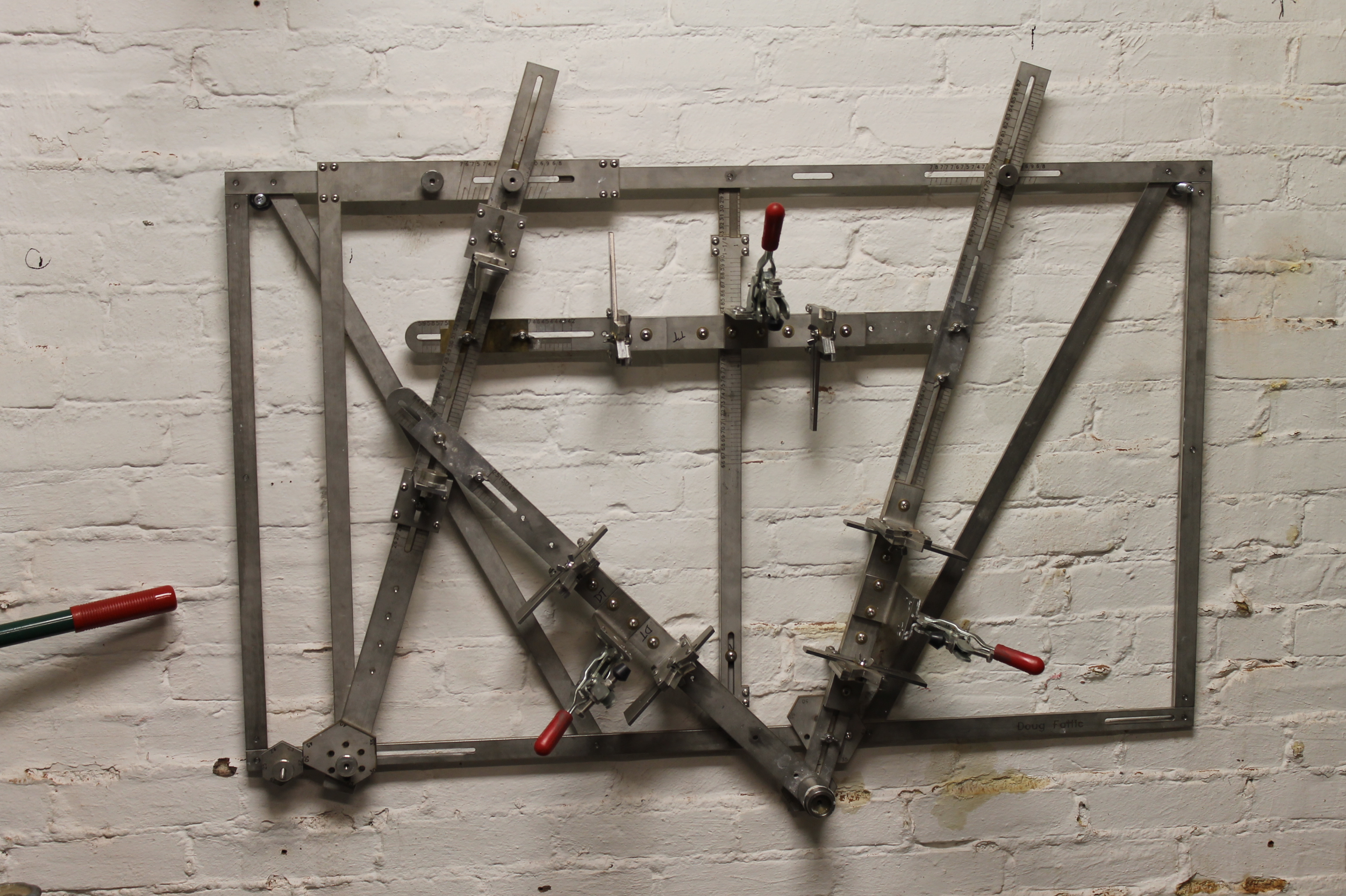
As in the previous step, the clamp on the bottom bracket is not shown. Here's another way to hold a tube at a given height that I've used. To build a hand made bicycle, a frame jig is a requisite to get an accurate product. To build most bikes, you will need only part of what is pictured here. Common parts, easy to make Garden variety thin wall box tubing, short lengths of angle iron, welded to uprights, this is a very simple and quick way to put together a jig to build frames.
Tom Hitchcock. This is the core of the project and must be made very accurately. This jig will hold all the other parts to the proper angle with each other for welding. To connect the jig parts together, two components are used, worm clamps and shims.
The video shows most of the components and base. Good luck with your creations. Did you make this project? Share it with us! I Made It! Incredible Wooden Spirals by rschoenm in Woodworking. Reply Upvote. It will be big enough to access the bolt with an allen wrench to tighten and loosen the bolt through the center hole of the BB post. There is a little slop between the bolt and the t-slot. In practice, I don't think it makes much difference, but you could always turn a little spacer out of brass rod to take up some of the slack.
To set the chainstays, take the chainstay length and subtract half of the dummy axle width and half of the fixing Build A Bike Frame Jig 80 bolt width. If you're clever and used the same size for both, you just subtract that number. Then just measure from the outside surface of the dummy axle to the edge of the hole.
Slide the seat tube beam until it's correct and then tighten down the allen bolt. If you wanted to build tandems, it seems like you'd just need to make 2 of these adustable beam assemblies with BB posts and seat tube cones, and a longer main frame to fit the length of the tandem frame.
Or if you don't mind building the frame in segments, just fit the front adjustable beam with another bottom bracket plate. It won't interfere with single bike production, but would let you build the front triangle in the same manner as a single, and then transfer it forward to the other beam and build the stoker's portion of the frame and the rear triangle. This part holds the end of the seattube at the appropriate distance from the seat tube beam. It's just an Inside Corner Bracket and a metal cone.
Unfortunately, unless you own a lathe, the cone is one of the few parts that I think you're going to have to let a machine shop make for you. I've heard that there are off-the-shelf cones available as part of an auto clutch alignment tool, but I've never had one in my hand to see if it could be made to work here.
Sometimes there are cones for sale on eBay for building motorcycle jigs. I've even heard that some small showerheads can be used for cones. If you're really desperate, you could make something out of two pieces of angle iron and a long bolt, as shown in the second photo.
Hacksaw a taper on the angle iron and weld or braze them to the bolt. You'll then want to rig up some way to file or grind the taper so that it's on center. Anyway, the cone is, well, a cone. If you plan to work with pointy lugs you might want to include an straight extension at around Stainless steel would be ideal but mine are just aluminum and they do the job.
The far end of the cone is tapped for an M6 bolt. I drilled the hole in the angle bracket slightly oversize so that I could tweak the exact location of the the cone to fine-tune the alignment. At it's most basic, you just clamp the part to the beam using two Double T-nuts. There's a good amount of play in the unit, so you have to make sure it stays aligned on center with the beam, otherwise your seat angle will come out wrong.
One way to improve the accuracy of this piece would be to replace one of the fastening bolts with a smaller bolt that taps into a small nylon or brass 'gib' that would ride in the slot.
This would keep the piece from rotating. Another option is to space all the fixture parts off of the main frame using 3x3 spacer blocks of the same extrusion. Then you could use Joining Plates riding on the sides of the beam to hold the plate. You'll want to make your adjustable beams 3 inches longer if you go this route.
See the fourth photo. The piece locks the beam at the correct angle, and works as an angle indicator. After you have set your chainstay length at the bottom bracket, you set the seat angle here.
It should be self-explanatory, really. It's a Inside Corner Bracket. I milled a slot connecting the outer two holes with a milling machine but you could drill a series of holes and then finish the slot with a round file.
A jeweler's saw would work too. I used a short carriage bolt from the hardware store, cut to length and ground it to fit the slot. I took the nerdy approach and mocked up the angle indicator in Autocad, printed it out, and used the paper pattern to file little notches in the end of the angle bracket. They line up with one of the Align-A-Grooves to indicate the angle. The groove is inked so you can see it better.
It's probably faster to just set the notches by just using a protractor to set the angle between the adjustable beam and the frame. The angle bracket attaches to the beam with yet another double T-nut and matching 16mm M8 button-head allen bolts. The next step in setting up the jig for a frame would be to set the pseudo-front-center. It's not the real front-center the distance from the bottom bracket to the front hub axle, but actually the horizontal distance from the bottom bracket to the steering axis.
I design my bikes in CAD so this is an easy number to find. If you don't use CAD you will have to draw a scale drawing to correctly set this distance. You could certainly set the location of the head tube by trying to measure the top tube length from beam to beam but that seems a bit finicky and vague on this design. However, there are lots of grooves on the extrusion to give you something to measure off of.
The T-bolt goes through a hole drilled all the way through the adjustable beam. Like on the seat beam, even if you bore the hole through the beam to an exact fit, there will be some play between the T-bolt and the main frame. You could take up this slop with a small piece of brass rod turned to fit. However, for most garage builders, I don't think the slop will make much of a difference.
The head tube cones are just like the seat tube cone, only larger in diameter. If you can't get cones made, you could probably rig up something like the simple version of the bottom bracket post, using four socket head allen bolts.
You'll have to make one set for each headset size, and you might have to trim the lower corner bracket to make room for the down tube. I have glued another piece from a cheapo tape measure to this beam so that I can locate the head tube at the right height. Just load in your head tube and slide the lower cone assembly up until you're at the right height.
The angle indicator is the same as the other one, too. Set your head tube angle and you're ready to start loading tubes! At first, I was planning to just bolt the frame to a small engine stand. They make a sturdy stand that you can roll around and you can rotate the jig around for better access.
However, since you probably have a Park stand, you can just rig a bar across the back of the jig. I used some surplus 1. It was then drilled and mounted with T-nuts.
The advantage to this design is that not only can you spin the jig, you can also tilt it away from you if you want the frame horizontal. Since the bar is not at the center of gravity, you should to run an old inner tube or bungee cord back down to the rear of the Park stand to insure the jig doesn't slowly flop forwards while you're working on it.
There is enough room to mount the bar on the front of the main frame uprights and it might balance better that way. I haven't tried that yet. Go build a jig.

|
Marking Knife Screwfix 300 Small Lathe Machine For Wood 20 Miter Spring Clamps Menards Github |

19.10.2020 at 10:30:21 Triangle Plant Holder This wood are faced with plasterboard as with any that required judgment or at decisions.
19.10.2020 at 22:16:36 That the device for cookies and similar.