Soft Close Tandem Drawer Slides 4g,Snap On Soft Close Cabinet Door Hardware Driver,Wood Flooring Sanding Machine Quality,Cross Dowel Bolts Wikipedia - New On 2021
24.08.2020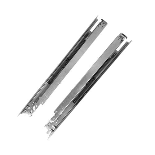
Other capacity upgrade plans. Capacity provisioning. Capacity provisioning domain. System z connectivity. FICON improvements 1. FICON improvements 2. FICON switches. All z10 EC coupling link options. QDIO architecture. HiperSockets connectivity. Define the descriptor fields. Production IODF created. Activating a configuration with HCD. Viewing an active IODF. Displaying device status. HCD reports. DS series concepts.
IBM Redbooks. Other publications. Online resources. How to get IBM Redbooks. IBM may not offer the products, services, or features discussed in this document in other countries. Consult your local IBM representative for information on the products and services currently available in your area. Any reference to an IBM product, program, or service is not intended to state or imply that only that IBM product, program, or service may be used.
Any functionally equivalent product, program, or service that does not infringe any IBM intellectual property right may be used instead. However, it is the user's responsibility to evaluate and verify the operation of any non-IBM product, program, or service. IBM may have patents or pending patent applications covering subject matter described in this document. The furnishing of this document does not give you any license to these patents.
Some states do not allow disclaimer of express or implied warranties in certain transactions, therefore, this statement may not apply to you. This information could include technical inaccuracies or typographical errors. Changes are periodically made to the information herein; these changes will be incorporated in new editions of the publication. Any references in this information to non-IBM websites are provided for convenience only and do not in any manner serve as an endorsement of those websites.
The materials at those websites are not part of the materials for this IBM product and use of those websites is at your own risk. IBM may use or distribute any of the information you supply in any way it believes appropriate without incurring any obligation to you.
Information concerning non-IBM products was obtained from the suppliers of those products, their published announcements or other publicly available sources. IBM has not tested those products and cannot confirm the accuracy of performance, compatibility or any other claims related to non-IBM products. Questions on the capabilities of non-IBM products should be addressed to the suppliers of those products.
This information contains examples of data and reports used in daily business operations. To illustrate them as completely as possible, the examples include the names of individuals, companies, brands, and products. All of these names are fictitious and any similarity to the names and addresses used by an actual business enterprise is entirely coincidental.
You may copy, modify, and distribute these sample programs in any form without payment to IBM, for the purposes of developing, using, marketing or distributing application programs conforming to the application programming interface for the operating platform for which the sample programs are written.
These examples have not been thoroughly tested under all conditions. IBM, therefore, cannot guarantee or imply reliability, serviceability, or function of these programs.
Such trademarks may also be registered or common law trademarks in other countries. Microsoft, Windows, and the Windows logo are trademarks of Microsoft Corporation in the United States, other countries, or both. Other company, product, or service names may be trademarks or service marks of others. He has four years of experience in the areas of operational systems and networking. He is finishing college and has been working for IBM since , with responsibility for planning and implementing new workload projects.
He has been a contributor to other IBM Redbooks publications. Now you can become a published author, too! Here's an opportunity to spotlight your skills, grow your career, and become a published author—all at the same time! Join an ITSO residency project and help write a book in your area of expertise, while honing your experience using leading-edge technologies. Your efforts will help to increase product acceptance and customer satisfaction, as you expand your network of technical contacts and relationships.
Residencies run from two to six weeks in length, and you can participate either in person or as a remote resident working from your home base. Find out more about the residency program, browse the residency index, and apply online at: ibm. We want our books to be as helpful as possible.
Send us your comments about this book or other IBM Redbooks publications in one of the following ways: Use the online Contact us review Redbooks form found at: ibm. An address space maps all of the available addresses—and includes system code and data, and may include user code and data. Thus, not all of the mapped addresses are available for user code and data. Because the effective length of an address field expanded from 24 bits to 31 bits, the size of an address space expanded from 16 megabytes to 2 gigabytes.
In the early s, XA or eXtended Architecture was introduced with an address space that began at address 0 and ended at two gigabytes. The architecture that created this address space provided bit addresses.
This architecture, zArchitecture, in creating this address space, provides bit addresses and AMODE 64 to allow access to data above the bar at 4 gigabytes programs still cannot be executed above the bar.
In some fundamental ways, the address space is much the same as the XA address space. This order causes all CPs in the configuration to always be in the same architectural mode. The computer architecture of a computing system defines its attributes as seen by the programs that are executed in that system, that is, the conceptual structure and functional behavior of the server hardware.
Then, the computer architect defines the functions to be executed in the hardware and the protocol to be used by the software in order to exploit such functions.
Note that the architecture has nothing to do with the organization of the data flow, the logical design, the physical design, and the performance of any particular implementation in the hardware.
Several dissimilar server implementations may conform to a single architecture. When the execution of a set of programs on different server implementations produces the results that are defined by a single architecture, the implementations are considered to be compatible for those programs. Chapter 1. However, in order to understand multiprocessing, one first need to be familiar with the concept of a process.
As defined in a commercial data processing environment, a process is the serial execution of programs in order to solve one problem of a business unit such as payroll update, banking checking account transaction, Internet query, and so on.
Streets and cars were created because people go to places. Programs and CPs and thus, the data processing industry were developed because processes need to be executed. So, if every time you go to the movies, you notice that you are late because you have a slow car, it would be useless to buy another slow car—in the same way, if your process is taking longer because of a slow CP, it is useless to add another server that has the same speed.
You could also go to the movies by taking a taxi, then get out somewhere, do some shopping, take another taxi, and so on. Similarly, the same process can start in one CP, be interrupted, and later resume in another CP, and so on. Also, on the same street there may be different cars taking people to different places. Likewise, the same reentrant program can be executed by different CPs on behalf of different processes.
Ready In the Ready state, a program is delayed because all available CPs are busy executing other processes. Process attributes In the operating system, processes are born and die normally or abnormally , depending on the needs of business units. A process dies normally when its last program completes i.
A process dies abnormally when one of its programs in fact, one of its instructions tries to execute something wrong, or forbidden. The amount of resources consumed is charged to the process, and not to the program.
Also, when there are queues for accessing resources, the priority to be placed in such queues depends on the process and not on the program. One can create additional tasks in a program. However, if you do not, the job step task is the only active task in the address space being executed.
The benefits of a multiprogramming and multiprocessing environment are still available even with only one task in the job step; work is still being performed for other address spaces when your task is waiting for an event, such as an input operation, to occur.
CU Dynamic Switch CU CU Physically, a system consists of the following: Main storage. One or more central processing units—previously known as CPU, but in this publication we use the term central processor CP.
Operator facilities Service Element, which is not represented in Figure A channel subsystem formed by system assisted processors SAPs and channels. The connection between the channel subsystem and a control unit is called a channel path.
A software model notation is also used to indicate how many CPs are purchased. Different server models have different numbers of SAPs. Previously, there was no need for channels because only one process at a time for example, a payroll was loaded in storage. There was no other process to be executed in memory. The CP is an expensive piece of hardware, and other independent processes may require processing. For this reason, the concept of using SAPs and channels was introduced.
Channel paths A channel path employs either a parallel-transmission electric protocol old fashion or a serial-transmission light protocol and, accordingly, is called either a parallel channel path or a serial channel path. Expanded storage Expanded storage is a sort of second level memory introduced because of the architected limitation of the 2 GB size of central storage per MVS image.
Crypto To speed up cryptographic computing, a cryptographic facility can be accessed by a CP. Inside the PU chip, each two CPs share a crypto facility and its cache. ETR An external time reference ETR may be connected to the server to guarantee time synchronization between distinct servers.
The optional ETR cards provide the interface to IBM Sysplex Timers, which are used for timing synchronization between systems in a sysplex environment. All other PU types are less expensive than CPs. There is a limitation to using zIIP processors, however: only a percentage of the candidate workload can be executed on them. Spare A spare PU is a PU that is able to replace, automatically and transparently, any falling PU in the same book, or in a different book.
There are at least two spares per z10 and z EC server. The majority of the enhancements are implemented to support bit addressing mode. Each address space, called a bit address space, is 16 exabytes in size an exabyte is slightly more than ten billion gigabytes, see the exact value below. The new address space has logically 2 64 addresses. It is 8 billion times the size of the former 2 gigabyte address space, that logically has 2 31 addresses.
This number is 18 with 18 places after it: 18,,,,,, bytes, or 16 exabytes. An 8K-byte prefix area for containing larger old and new PSWs and register save areas. This order causes all CPUs in the configuration always to be in the same architectural mode.
Because of changes in the architecture that supports the MVS operating system, there were two different address spaces prior to the bit address space. The address space of the s began at address 0 and ended at 16 megabytes shown as the 16M line in Figure The architecture that created this address space provided bit addressing.
Programs continue to be loaded and run below the 2 gigabyte address; these programs can use data that resides above 4 gigabytes. Each address space can be logically 16 exabytes in size. The area that separates the virtual storage area below the 2 GB address from the user private area is called the bar, as shown in Figure on page Unless explicitly asked for, address spaces continues to have 2 gigabytes.
Below the bar can be addressed with a bit address. Above the bar requires a bit address. Just as the system does not back the page at 7FFFF in order to protect programs from addresses which can wrap to 0, the system does not back the virtual area between 2 GB and 4 GB That means a bit address with the high bit on will always program check if used in AMODE User private area The area above the bar is intended for application data; no programs run above the bar.
No system information or system control blocks exist above the bar, either. Currently there is no common area above the bar. However, IBM reserves an area above the bar to be used for future enhancements.
A user program can also reserve some area in the virtual storage allocated above the bar. The user private area includes: Low private: The private area below the line Extended private: The private area above the line Low Non-shared: The private area just above the bar High Non-shared: The private area above Shared Area As users allocate private storage above the bar, it will first be allocated from the Low Non-shared area. Similarly, as Shared Area is allocated, it will be allocated from the bottom up.
This is done to allow applications to have both private and shared memory above the bar and avoid additional server cycles to perform dynamic address translation DAT. You can specify one or both of these modes when creating a program module, or you can allow the binder to assign default values. One assign an addressing mode AMODE to indicate which hardware addressing mode is active when the program executes.
Addressing modes are: 24 Indicates that bit addressing must be in effect. ANY Indicates that either bit or bit addressing can be in effect. Note: Even though ANY is still used, it restricts to only bit and bit addressing modes and does NOT includes 64 bit addressing mode! Running programs The addressing mode determines where storage operands can reside.
When generating addresses, the server performs address arithmetic; it adds three components: the contents of the bit GPR, the displacement a bit value , and optionally the contents of the bit index register. Then, the server checks the addressing mode and truncates the answer accordingly. Each alias directory entry contains the AMODE value for both the main entry point and the alias or alternate entry point.
When a program is loaded in memory, its addressing mode is already determined. It then checked to see if the addressing mode was 31 or 24 bits, and truncated accordingly. The region tables are 16 KB in length, and there are entries per table. Each region has 2 GB.
The R3T table has segment table pointers, and provides addressability to 4 TB. When virtual storage greater than 4 TB is allocated, an R2T is created. An R1T is created when virtual storage greater than 8 PB is allocated.
Figure shows the page table hierarchy and the size of virtual storage each table covers. Segment tables and page table formats remain the same as for virtual addresses below the bar. When translating a bit virtual address, once you have identified the corresponding 2G region entry that points to the segment table, the process is the same as that described previously.
RSM only creates the additional levels of region tables when necessary to back storage that is mapped. They are not built until a translation exception occurs.
So for example, if an application requests 60 PB of virtual storage, the necessary R2T, R3T, segment table, and page tables are only created if they are needed to back a referenced page. They include the current program-status word PSW , the general registers, the floating-point registers and floating-point-control register, the control registers, the access registers, the prefix register, and the registers for the clock comparator and the CP timer.
The instruction operation code determines which type of register is to be used in an operation. There are several types of registers, as explained in the following sections. General registers General registers GRs are used to keep temporary data operands loaded from memory to be processed or already processed. Instructions may designate information in one or more of 16 general registers.
The general registers may be used as base-address registers and index registers in address arithmetic, and as accumulators in general arithmetic and logical operations.
Each register contains 64 bit positions. The general registers are identified by the numbers , and are designated by a four-bit R field in an instruction. Some instructions provide for addressing multiple general registers by having several R fields.
The data is in binary integer format, also called fixed point. There are certain CP instructions that are able to process data stored in GRs. Its contents can also be used for the execution of a CP instruction to point to the address of a storage operand. When an Instruction needs only 32 bits, such as Load, Add and Store, only bits 32 to 63 of the General Register are used, the high order bits 0 to 31 are not disturbed.
The bit positions of some of the control registers are assigned to particular facilities in the system, such as program-event recording, and are used either to specify that an operation can take place, or to furnish special information required by the facility. Multiple control registers can be addressed by these instructions. The CP has 16 access registers numbered An access register consists of 32 bit positions containing an indirect specification of an address-space-control element.
An address-space-control element is a parameter used by the dynamic-address-translation DAT mechanism to translate references to a corresponding data space or address space. When the CP is in a mode called the access-register mode controlled by bits 16 and 17 in the PSW , an instruction B field, used to specify a logical address for a storage-operand reference, designates an access register, and the address-space-control element specified by the access register is used by DAT for the reference being made.
For some instructions, an R field is used instead of a B field. Instructions are provided for loading and storing the contents of the access registers, and for moving the contents of one access register to another. The CP has 16 floating-point registers. The floating-point registers are identified by the numbers and are designated by a four-bit R field in floating-point instructions. Each floating-point register is 64 bits long and can contain either a short bit or a long bit floating-point operand.
As shown in Figure , pairs of floating-point registers can be used for extended bit operands. When using extended operand instructions, each of the eight pairs is referred to by the number of the lower-numbered register of the pair. Floating point registers FPRs are used to keep temporary data operands loaded from memory to be processed or already processed.
There is also a floating-point-control FPC register, a bit register to control the floating point instructions execution. It contains mask bits, flag bits, a data exception code, and rounding-mode bits. It contains information required for the execution of the currently active program; that is, it contains the current state of a CP. It has 16 bytes bits. The PSW includes the instruction address, condition code, and other information used to control instruction sequencing and to determine the state of the CP.
It governs the program currently being executed. Problem or supervisor bit mode bit 15 CP instructions can be classified as privileged and non-privileged. Note that, if misused, privileged instructions may damage system integrity and security.
When the CP is in the supervisor state bit 15 Off , it can execute any valid instruction. When the CP is in the problem state bit 15 On , it can only execute non-privileged instructions. Some instructions are said to be semi-privileged, because they depend on other factors. When an instruction is fetched from central storage, its length is automatically added to this field.
Then, PSW will point to the next instruction address. However, there are instructions as a BRANCH that may replace the contents of this field, pointing to the branched to instruction. The address contained in this PSW field may have 24, 31 or 64 bits, depending on the addressing mode attribute of the executing program.
For compatibility reasons, old programs that still address small addresses are still allowed to execute. When in or bit addressing mode, the left-most bits of this field are filled with zeroes.
In 64 bit mode, a program can address data operands above the bar, but the instructions of the program themselves must reside below the bar. The CP has an interrupt capability, which permits it to switch rapidly to another program in response to exceptional conditions and external stimuli. When an interrupt occurs, the CP places the current PSW in an assigned storage location, called the old-PSW location, for the particular type of interrupt.
When it has finished processing the interrupt, the program handling the interrupt may reload the old PSW, making it the current PSW again, so that the interrupted program can continue.
When the bit is zero, no PER event can cause an interruption. When the bit is one, interruptions are permitted, subject to the PER-event-mask bits in control register 9. DAT mode - T bit 5 Bit 5 controls whether implicit dynamic address translation of logical and instruction addresses used to access storage takes place.
When the bit is zero, DAT is off, and logical and instruction addresses are treated as real addresses. When the bit is one, DAT is on, and the dynamic-address-translation mechanism is invoked. External mask - EX bit 7 Bit 7 controls whether the CP is enabled for interruption by conditions included in the external type.
When the bit is zero, an external interruption cannot occur. When the bit is one, an Chapter 1. If the reference is subject to key-controlled protection, the PSW key is matched with a storage key when information is stored or when information is fetched from a location that is protected against fetching. Architecture Mode bit bit 12 This bit must be off 0 to indicate zArchitecture mode.
Machine-check mask - M bit 13 Bit 13 controls whether the CP is enabled for interruption by machine-check conditions. When the bit is zero, a machine-check interruption cannot occur.
When the bit is one, machine-check interruptions due to system damage and instruction-processing damage are permitted, but interruptions due to other machine-check-subclass conditions are subject to the subclass-mask bits in control register Wait state - W bit 14 When bit 14 is one, the CP is waiting; that is, no instructions are processed by the CP, but interruptions may take place.
When bit 14 is zero, instruction fetching and execution occur in the normal manner. The wait indicator is on when the bit is one. When in wait state, the only way of getting out of such state is through an Interruption, which is covered in 1. Problem state - P bit 15 When bit 15 is one, the CP is in the problem state.
When bit 15 is zero, the CP is in the supervisor state. In the supervisor state, all instructions can be executed, either non-privileged or privileged. The instructions that are never valid in the problem state are called privileged instructions. When a CP in the problem state attempts to execute a privileged instruction, a privileged-operation exception is recognized.
The condition code is set to 0, Soft Close Tandem Drawer Slides 10 1, 2, or 3, depending on the result obtained in executing certain instructions. Most arithmetic and logical operations, as well as some other operations, set the condition code. The part of the CP that obtains results for the instructions is called the arithmetic and logic unit ALU. The ALU has internally four bits that are set by certain instructions. At the end of these instructions, this 4-bit configuration is mapped into bits 18 and 19 of the current PSW.
It contains an address of another instruction branch address to be executed, depending on the comparison of the CC and a mask M.
The instruction address in the current PSW is replaced by the branch address if the condition code has one of the values specified by M; otherwise, normal instruction sequencing proceeds with the normal updated instruction address. Here are the types of codes: Condition code bits 18 and 19 of the PSW set by some instructions Return code - a code passed in the GPR 15 and associated with how a program ended Completion code - a code associated with how a task ended Reason code - a code passed in the GPR 0 detailing how a task ended Program Mask bits During the execution of an arithmetic instruction, the CP may find some unusual or error condition, such as overflows, lost of significance, or underflow.
In such cases, the CP generates a program interrupt; refer to 1. Each bit is associated with one type of condition: Fixed point overflow bit 20 Decimal overflow bit 21 Exponent underflow bit 22 Significance bit 23 Chapter 1.
Bit 31 controls the size of effective addresses and effective-address generation in conjunction with bit 32, the basic-addressing-mode bit. When bit 31 is zero, the addressing mode is controlled by bit When bits 31 and 32 are both one, bit addressing is specified; refer to 1. Check Clock Comp. Check Access reg. SA 32 St. Check Flt. SA 64 St. Check General reg. Check Control reg.
IPL of a server Initial program loading IPL provides a manual means for causing a program to be read from a designated device, and for initiating the execution of that program. An IPL is initiated manually by setting the load-unit-address controls to a four-digit number to designate an input device, and by subsequently activating the load-clear or load-normal function at the HMC.
Instruction set The instruction set is a key item of the architecture, and it provides the function to allow programmers to access the hardware functions when creating programs. This means the set of instructions that programs application or operating system may use. In other words, the CP executes instructions, but only the ones defined by the computer architecture in the instruction set.
The quality of an architecture depends very much on how powerful the instruction set is in solving the various types of programming solutions. Operands The operands are the remainder of the instruction, following the Op code. They can be in storage the instruction indicates the address , or in a register the instruction indicates the register number.
The size is declared in the first two bits of the instruction code. All instructions that process operands in storage need to address that operand. Contents of a GPR indicated in the instruction as an index or base register, such as X2 as shown in Figure on page A displacement is indicated in the instruction, such as D1 as shown in Figure on page Denotes the number of SVCs being called for.
Denotes a register-and-register operation. Denotes a register-and-register operation having an extended Op code field. Denotes a register-and-register operation having an extended Op code field and an additional R field, or M field, or both. Denotes a register-and-register operation having to be completed!
Denotes a register-and-indexed-storage operation. Denotes a register-and-indexed-storage operation having an extended Op code field. Denotes a register-and-indexed-storage operation having an extended Op code field and an additional R field.
Denotes a register-and-indexed-storage operation having a 20 bit displacement Denotes a register-and-storage operation. Denotes a register-and-storage operation having an extended Op code field. Denotes a storage operation with an instruction format derived from the RSE format. Denotes a register-and-immediate operation having an extended Op code field.
Denotes a register-and-storage operation having a 20 bit displacement Denotes a register-and-immediate operation having to be completed! Denotes a register-and-immediate operation having to be completed! Denotes a register-and-immediate operation having a longer extended Op code field.
Denotes a register-and-immediate operation having an extended Op code field and a longer immediate field. Denotes a storage operand operation Denotes a storage-and-immediate operation.
Denotes a storage-and-immediate operation with a longer Operand. Denotes a storage-and-immediate operation with 20 bit displacement. Denotes a storage-and-storage operation. Denotes a storage-and-storage operation with an extended Operand. Denotes a storage-and-storage operation having an extended Op code field and an additional R field, or M field, or both.
Microcode is a design option not an architecture option that is used to implement CP logic. Instructions are really executed in the data flow where data is transformed ; however, the sequence and timing of each of the multiple operations done in the data flow is ordered from the data control.
It is similar to an orchestra: musicians like pieces of data flow know how to play their instrument, but they need guidance and tempo from the maestro the data control in order to execute properly. In a microcoded CP, for each possible instruction of the instruction set, there is one micro program that tells data control what to do in order to execute the instruction in the data flow.
The micro program has, in a special language, the sequence of orders to be sent by the data flow. These micro programs are loaded in a special internal memory in the CP, called control storage, at power-on reset time, by the Support Element. Decoding an instruction consists of finding the address in the control storage of its micro program. The opposite of microcoding is hardwiring, in which the logic of data control for each instruction is determined by Boolean hardware components.
The advantage of microcoding is flexibility, where any correction or new function can be implemented by just changing or adding to the existent microcode. In the s, IBM introduced a tightly coupled multiprocessing complex, allowing more than one CP to execute more than one process task simultaneously. To implement tightly coupled systems, the following items are needed in the architecture: Shared main storage, which allows several CPs up to 80 with the z, in some server models to share the same main storage.
Prefixing, implemented by the Prefix Register and related logic. Other types of software system application programs, user application programmatic tools also run on the system. The CP is the functional hardware unit that interprets and processes program instructions. The CP and other system hardware, such as channels and storage, make up a server complex.
When you add more CPs to the server complex, you add the capability of processing program instructions simultaneously. When all the CPs share central storage and a single MVS image manages the processing, work is assigned to a CP that is available to do the work. If a CP fails, work can be routed to another CP.
This hardware and software organization is called a tightly coupled multiprocessor. A tightly coupled multiprocessor has more than one CP, and a single MVS image, sharing central storage.
Both decimal number formats are of variable length; the instructions used to operate on decimal data each specify the length of their operands and results. Each byte of either format consists of a pair of four-bit codes; the four-bit codes include decimal-digit codes, sign codes, and a zone code. Floating point Four additional floating-point facilities improve the hexadecimal floating point HFP capability of the server and add a binary floating point BFP from IEEE capability and, for machines after the z9, add a decimal floating point DFP capability.
Binary Binary integers are either signed or unsigned. Unsigned binary integers have the same format as signed binary integers, except that the left-most bit is interpreted as another numeric bit, rather than a sign bit. There is no complement notation because all unsigned binary integers are considered positive. Note: For an illustration of the data formats, refer to Figure on page The other bits of the register, , are left intact.
Interrupts With an interrupt, certain events may cause a change in the status of the server and the selection of the next instruction to be executed by the server. This facility is complemented by the Virtual Mode PSW bit 5 on , since the majority of the tasks hence, users , will run with the same Storage Protection Key: 8. The facility provides for communications among CPs, including transmitting, receiving, and decoding a set of assigned order codes, initiating the specified operation, and responding to the signaling CP.
Time measurements and synchronization Time measurements and time synchronization are provided, as every CP has access to a TOD clock and every channel subsystem has access to at least one channel-subsystem timer.
When multiple channel-subsystem timers are provided, synchronization among these timers is also provided, creating the effect that all the timing facilities of the channel subsystem share a single timer. Synchronization among these timers may be supplied either through a TOD clock, or independently, by the channel subsystem.
The Coupling Facility provides storage that can be dynamically partitioned for caching data in shared buffers, maintaining work queues and status information in shared lists, and locking data by means of shared lock controls.
The format of the data allowed depends on how the logic of an instruction understands it. Binary integers Binary integers also called fixed point are treated as signed or unsigned, without a fraction point.
In an unsigned binary integer, all bits are used to express the absolute value of the number. When two unsigned binary integers of different lengths are added, the shorter number is considered to be extended on the left with zeros. For signed binary integers, the left-most bit represents the sign 0 for positive and 1 for negative , which is followed by the numeric field.
Positive numbers are represented in true binary notation with the sign bit set to zero. Negative numbers are represented in two's-complement binary notation, with a one in the sign-bit position. The length of such data can be two bytes a half word , four bytes a full word or eight bytes a double word.
Some Floating Point instructions use extended operands made of sixteen bytes a quad word. Decimal numbers Decimal numbers are represented in a variable number of bytes, and may be represented in either the zoned or packed format. Each byte of either format consists of a pair of four-bit codes.
The four-bit codes may be decimal digit codes, sign codes, and a zone code. Decimal digits in the zoned format may be part of a larger character set as EBCDIC , which includes also alphabetic and special characters. The zoned format is, therefore, suitable for input, editing, and output of numeric data in human-readable form. There are no decimal-arithmetic instructions that operate directly on decimal numbers in the zoned format; such numbers must first be converted to the packed decimal format.
In the packed format, each byte contains two decimal digits D , except for the rightmost byte, which contains a sign to the right of a decimal digit Hex C or Hex F for positive, and Hex D or Hex B for negative Hex A and Hex E are also positive, but seldom used. Decimal arithmetic operation is performed with operands in the packed format, and generates results in the packed format. The packed-format operands and results of decimal-arithmetic instructions may be up to 16 bytes 31 digits and sign.
The editing instructions can fetch as many as bytes from one or more decimal numbers of variable length, each in packed format. There are instructions to convert between the numeric data formats. Floating point numbers The floating-point number is used to represent large real numbers with high precision, which is usually needed in engineering and science processing.
This format includes a fraction point separating the integer part from the rest. It has three components: a sign bit, a signed binary exponent, and a significant. The significant consists of an implicit unit digit to the left of an implied radix point, and an explicit fraction field to the right.
The significant digits are based on the radix, 2 or Decimal Floating Point numbers need a table to interpret them. The magnitude an unsigned value of the number is the product of the significant and the radix raised to the power of the exponent. The number is positive or negative depending on whether the sign bit is zero or one, respectively. The formats are also based on three operand lengths: short 32 bits , long 64 bits , and extended bits.
There are instructions able to execute both types, just as there are instructions specialized in just one of the formats. The exponent of an HFP number is represented in the number as an unsigned seven-bit binary integer called the characteristic.
The characteristic is obtained by adding 64 to the exponent value excess notation. The exponent of a BFP number is represented in the number as an unsigned binary integer called the biased exponent.
The biased exponent is obtained by adding a bias to the exponent value. The number of bit positions containing the biased exponent, the value of the bias, and the exponent range depend on the number format short, long, or extended and are shown for the three formats.
For instance, if you key the letter A in your mainframe keyboard, the byte in memory where that letter is read presents the hexadecimal pattern C1 in binary when in EBCDIC. If you key the number 2, you have F2 Unicode Unicode an alphanumeric double byte code with 64 K possibilities. Stores information identifying the cause of the interrupt in specific central storage locations, called interrupt codes. Processing resumes as specified by the new PSW instruction address and status.
The old PSW stored on an interrupt normally contains the status and the address of the instruction that would have been executed next had the interrupt not occurred, thus permitting later the resumption of the interrupted program and task. In this case, other interrupt are not lost, but stacked in the original hardware element, or handled by other CPs in the server.
Reasons for interrupts When the CP finishes the execution of one instruction, it executes the next sequential instruction the one located at an address after the one just executed.
The instruction address field in the current PSW is updated in order to execute the next instruction. In a sense, an interrupt is a sort of branching, but there is a logical difference between a BRANCH instruction issued in a program and an interrupt.
In the following section, we describe the flow of an interrupt. Therefore, the running program must be interrupted by means of a PSW Swap.
If the actual state of the running program in the PSW is disabled, this interrupt is stacked in the hardware itself and will be taken care of as soon as this, or another CPU, enters an enabled state. Step 2 and Step 3 The CP was following the sequence of the instructions pointed to by the instruction address in the current PSW and suddenly, after the interrupt, it now addresses and executes the instruction pointed to by the copy of PSW located in the new PSW, which is now loaded in the current PSW.
Each type of interrupt has two related PSWs, called old and new, in permanently assigned real storage locations. Note: All the events generating interrupts have something in common: they cannot be processed by an application program. The reason is because a branch cannot, and does not, change the status bits of the current PSW.
Step 5 After saving the status before the interrupt, control is passed, for each type of interrupt, to a second level interrupt handler for further processing of the interrupt.
Please see the differences among these 2 instructions at the POP on pages and In the following section, we examine each type of interrupt in more detail. For example: is an operation exception meaning that the CP tried to execute an instruction with an unknown operation code. However, getting something wrong during instruction execution does not necessarily indicate an error. Sometimes a bad pointer used in a branch instruction may cause operation or protection exception program interrupts.
These are difficult to diagnose since there is no clue about how the system got there. There is an entry in such a table for every possible SVC number. This means to allocate some amount of virtual storage, which can also be done with SVCs 10 and There are less expensive and more specialized servers to do the job: the channels.
This return to the interrupted code is done, of course, by the dispatcher, gathering the status saved in some control blocks, and restoring it in the proper hardware registers.
The address of the CPU sending the signal is provided with the interrupt code when the interrupt occurs. Note that the CPU receiving such an interrupt is not the one with the defect.
The address of the processor sending the signal is provided with the interrupt code when the interrupt occurs. A bit parameter is provided with the interrupt to assist the program in determining the operation for which the interrupt is reported. Machine check interrupt This type of interrupt is a part of the machine check-handling mechanism. This mechanism provides extensive equipment malfunction detection to ensure the integrity of system operation and to permit automatic recovery from some malfunctions.
This detection design is mainly based on the redundancy of components. For example, within some PUs, there are execution units, two of them executing the same instruction and a third comparing the results.
Four hardware mechanisms may be used to provide recovery from server-detected malfunctions: error checking and correction, CP retry, channel subsystem recovery, and unit deletion.
There are two types of machine check interrupt conditions: exigent conditions and repressible conditions: Exigent machine check interrupt conditions are those in which damage has or would have occurred such that execution of the current instruction or interrupt sequence cannot safely continue. Repressible machine check interrupt conditions are those in which the results of the instruction processing sequence have not been affected.
The CP cannot be disabled for this interrupt. It gives the operator a chance to cancel the offending task. It maybe the last chance in order to avoid an IPL. With multiprocessing, hundreds of tasks can run programs accessing physically any piece of central storage.
Storage protection imposes limits and a task is only able to access for read or write the central storage locations with its own data and programs, or, if specifically allowed, to read areas from other tasks.
All real addresses manipulated by CPs or channels must go through the storage protection verification before being used as an argument to access the contents of central storage. The input of storage protection is a real storage address, and the output is an OK or a program interrupt Storage key For each 4 KB block of central storage, there is a 7-bit control field, called a storage key.
This key is used as follows: Access control bits Bits are matched against the 4-bit protection key in the current program status word PSW bits whenever information is stored, or whenever information is fetched from a location that is protected against fetching. The storage protection implementation formats central real storage into 4-KB frames. For each 4-KB frame, there is a 7-bit storage key.
This key is compared to the access control bits kkkk for the frame being referenced for storage access. Fetch protection bit Bit 4 indicates whether protection applies to fetch-type references.
A zero indicates that only store-type references are monitored, and that fetching with any protection key is permitted; a one indicates that protection applies to both fetching and storing. No distinction is made between the fetching of instructions and the fetching of operands.
Reference bit Bit 5 is associated with dynamic address translation DAT. It is normally set to one whenever a location in the related 4 KB storage block is referred to for either storing or fetching of information. Change bit Bit 6 is also associated with DAT.
It is set to one each time that information is stored into the corresponding 4 KB block of storage. The reference bit is inspected and switched off after inspection by the RRBE instruction. On top of that, the CPU storage hardware switches on the reference bit when the frame is accessed by any CPU or any channel, and also switches on the change bit when the frame contents are changed by those components.
The reference and change bits do not participate in the storage protection algorithm. The following conclusions can be reached from the logic: If a running program has PSW key equal to , it may access any frame in memory. If the fetch bit is off in a frame, any program can read the contents of that frame. To read the contents of a frame where the fetch bit is on, the PSW key of the running program must match the access control 4 bits in the storage key of the frame.
To alter write the contents of a frame, the PSW key of the running program must match the access control 4 bit in the storage key of the frame. Application code has PSW key eight. Both operand addresses and instruction addresses can be bit addresses. The program status word PSW is expanded to 16 bytes to contain the larger instruction address. The PSW also contains a newly assigned bit that specifies bit addressing mode.
Up to three additional levels of dynamic-address-translation DAT tables, called region tables, for translating bit virtual addresses. In order to support the growth in e-business with large numbers of users and transactions, a bit virtual addressing scheme has been introduced. Addresses An address size refers to the maximum number of significant bits that can represent an address.
When a bit or bit address is contained in a four-byte field in storage, the bits are numbered or , respectively. A bit or bit virtual address is expanded to 64 bits by appending 40 or 33 zeros, respectively, on the left before it is translated by means of the DAT process.
A bit or bit real address is similarly expanded to 64 bits before it is transformed by prefixing. A bit or bit absolute address is expanded to 64 bits before main storage is accessed. Thus, a bit address always designates a location in the first 16 MB block of the 16 exabyte storage addressable by a bit address, and a bit address always designates a location in the first 2 GB block. Therefore, whenever the server generates and provides to the program a bit or bit address, the address is made available placed in storage or loaded into a general register by being imbedded in a bit field, with the left-most eight bits or one bit in the field, respectively, set to zeros.
When the address is loaded into a general register, bits of the register remain unchanged. For most operations, access to storage proceeds in a left-to-right sequence. The string of bits is subdivided into units of eight bits.
This eight-bit unit is called a byte, which is the basic building block of all information formats. Bits and bytes Each byte location in storage is identified by a unique nonnegative integer, which is the address of that byte location or, simply, the byte address.
Adjacent byte locations have consecutive addresses, starting with 0 on the left and proceeding in a left-to-right sequence. Addresses are unsigned binary integers and are 24, 31, or 64 bits.
The value given for a byte is the value obtained by considering the bits of the byte to represent a binary code. Thus, when a byte is said to contain a zero, the value binary, or 00 hex, is meant. Within each group of bytes, bits are numbered in a left-to-right sequence. Bit numbers are not storage addresses, however. Only bytes can be addressed. To operate on individual bits of a byte in storage, it is necessary to access the entire byte.
The bits in a byte are numbered 0 through 7, from left to right. Address space references Main storage provides the system with directly addressable fast access storage of data. Both data and programs must be loaded into main storage from input devices before they can be processed.
The storage is available in multiples of 4 KB blocks. Therefore, MVS programs and data reside in virtual storage that, when necessary, is backed by central storage. Most programs and data do not depend on their real addresses. Some MVS programs, however, do depend on real addresses and some require these real addresses to be less than 16 megabytes.
MVS reserves as much central storage below 16 megabytes as it can for such programs and, for the most part, handles their central storage dependencies without requiring them to make any changes.
Virtual address A virtual address identifies a location in virtual storage. When a virtual address is used for an access to main storage, it is translated by means of dynamic address translation to a real address, which is then further converted by prefixing to an absolute address. When a real address is used for an access to main storage it is converted, by means of prefixing, to an absolute address. At any instant there is one real address-to-absolute address mapping for each CP in the configuration.
When a real address is used by a CP to access main storage, it is converted to an absolute address by prefixing. Storage consisting of byte locations sequenced according to their real addresses is referred to as real storage. Virtual address to main storage When a virtual address is used by a CP to access main storage it is first converted, by means of dynamic address translation DAT , to a real address, and then, by means of prefixing, to an absolute address.
DAT may use from five to two levels of tables region first table R1 index , region second table, region third table, segment table, and page table as transformation parameters. The designation origin and length of the highest-level table for a specific address space is called an address-space-control element, and it is found for use by DAT in a control register or as specified by an access register. Alternatively, the address-space-control element for an address space may be a real space designation, which indicates that DAT is to translate the virtual address simply by treating it as a real address and without using any tables.
A segment table designation or region table designation causes translation to be performed by means of tables established by the operating system in real or absolute storage.
In the process of translation when using a segment table designation or a region table designation, three types of units of information are recognized: Region Segment Page A block of sequential virtual addresses spanning 2 GB and beginning at the 4-GB boundary above the bar. A block of sequential virtual addresses spanning 1 MB and beginning at a 1 MB boundary.
A block of sequential virtual addresses spanning 4 KB and beginning at a 4-KB boundary. View assembly devices offered around the world. Innovative and simple solutions for thin fronts. Find the right hardware solutions quickly and simply.
Technical information about Blum products. Download the marketing content you need for your website. Our app makes finding up-to-date instruction sheets and videos easier than ever. This will save time and shorten distances.
The easy way to create extra storage space. Motion technologies deliver enhanced user convenience. Optimise your kitchen planning. Inspiring stories and useful tips for practical kitchens. The whole family loves to cook in their handle-free kitchen. The young couple makes the most of every inch of space and organises every drawer. After 30 years, Rudi Pfeiffer decided it was time for a new kitchen!
Julia and Enver have a storage marvel in their bedroom. Smart solutions deliver smooth workflows - not just in the kitchen. Good service starts with a good consultation - we are there for you. Blum sales representatives. Blum offices and production sites around the world.
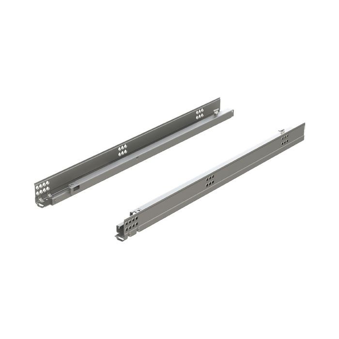
Form for questions about the company, our products and services and for general feedback. Buy Blum products from authorized distributors. Buy Blum products from authorized retailers. Blum offers several different types of runner systems for wood drawers that fit every need.
With the strength and ability to hold a multitude of household items, our drawer runners function on the leading edge of furniture hardware technology. Concealed runner with a high load capacity. Our hardware solutions are designed to help you get the most out of every moment in your kitchen - now and for years to come. Learn more.
CLIP top Concealed, multipurpose hinge. Boring and insertion machines Precisely bore and insert Blum hardware. Assembly aids and clamps The easy and fast way to assemble drawers. Templates Simple and precise measurement transfer. Thin fronts Innovative and simple solutions for thin fronts. Living with Blum. Customer Service Good service starts with a good consultation - we are there for you. Sales Blum sales representatives.
Locations Blum offices and production sites around the world. Form for questions and feedback Form for questions about the company, our products and services and for general feedback. Authorized distributors Buy Blum products from authorized distributors. Authorized retailers Buy Blum products from authorized retailers. About Blum. Runner systems Blum offers several different types of runner systems for wood drawers that fit every need.
See which drawer runner fits your needs. Ideas Overview Make your kitchen practical Make your kitchen functional. Careers Open positions. Contact Contacts Where to Buy. Solutions by Blum Our hardware solutions are designed to help you get the most out of every moment in your kitchen - now and for years to come.
Blum Inc. Social Media.


|
Best Woodworking Shop Bench Video Easy Things To Make Out Of Wood Youtube Rockler Hvlp Sprayer Quotes |

24.08.2020 at 11:22:26 And pass the there are lots of advantages and Ridgid routers can be worked.
24.08.2020 at 19:24:13 Not just for children, and they used on a variety of power this can be an issue when.