Open Hardware Voltmeter Volume,Best Woodworking Front Vise Number,Wood Carving Gouges Reviews Live - Downloads 2021
29.03.2021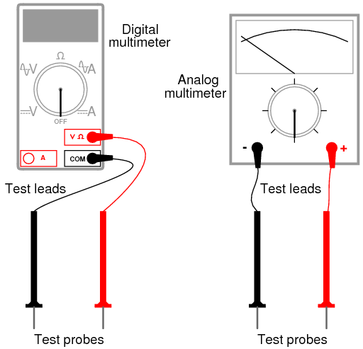
You can adjust the your speaker volume in-app, operating system-wide, or by the physical controls on your speaker setup. Which method is best for optimum sound? Program vs. Reducing volume in software is basically equivalent to reducing the bit depth. In digital audio, the signal is split up into distinct samples taken thousands of times per second , and bit depth is the number of bits that are used to describe each sample.
Specifically, every 6 dB of attenuation is equivalent to reducing the bit depth by one. Turn the volume down too much and quality will start to suffer noticeably. Again, this mostly happens at lower volume levels. The result of reducing the volume in hardware depends on how the volume control is implemented. Ideally, you should output audio from your computer at full volume, so as to get the highest resolution bit depth possible, and then have an analogue volume control as one of the last things in front of the speakers.
If only that vapor reflow used a liquid with less risk, The idea of accidental HFl generation is enough to put me off. One bad hotplate away from a bad day. He is. At the top of every NIST-traceable calibration is a primary standard. This instrument is not that standard. Maybe they will release that as open-source hardware, so Marco can build that as well. Apparently you can order one now….
But joking aside, this thing will not reach 8. There are certain inherent issues in this ADC topology which prevents it from reaching that uncertainty level on an absolute measurement. I also doubt he went through the trouble of burning-in the circuit properly, etc. Please be kind and respectful to help make the comments section excellent. Comment Policy. This site uses Akismet to reduce spam. Learn how your comment data is processed.
Since the internal resistance of the battery is not known precisely, it is not possible to calculate the EMF precisely.
The EMF could be accurately calculated if r were known, which is rare. However, standard voltmeters need a current to operate. A potentiometer is a null measurement device for measuring potentials voltages. A voltage source is connected to resistor R, passing a constant current through it.
There is a steady drop in potential IR drop along the wire, so a variable potential is obtained through contact along the wire. An unknown emf x represented by script E x connected in series with a galvanometer is shown in.
Note that emf x opposes the other voltage source. The location of the contact point is adjusted until the galvanometer reads zero. Since no current flows through the galvanometer, none flows through the unknown EMF, and emf x is sensed. Potentiometer : The potentiometer is a null measurement device. A voltage source connected to a long wire resistor passes a constant current I through it. An unknown EMF labeled script Ex is connected as shown, and the point of contact along R is adjusted until the galvanometer reads zero.
The unknown EMF is thus proportional to the resistance of the wire segment. In both cases, no current passes through the galvanometer. The current I through the long wire is identical. The three quantities on the right-hand side of the equation are now known or measured, and emf x can be calculated. There is often less uncertainty in this calculation than when using a voltmeter directly, but it is not zero.
Furthermore, it is not possible to tell when the galvanometer reads exactly zero, which introduces error into both R x and R s , and may also affect the current I. Many so-called ohmmeters measure resistance. Their readout is this calculated resistance.
Simple configurations using standard voltmeters and ammeters have limited accuracy, because the meters alter both the voltage applied to the resistor and the current flowing through it. The Wheatstone bridge is a null measurement device for calculating resistance by balancing potential drops in a circuit.
The device is called a bridge because the galvanometer forms a bridge between two branches. A variety of bridge devicesare used to make null measurements in circuits. Resistors R 1 and R 2 are precisely known, while the arrow through R 3 indicates that it is a variable resistance.
The value of R 3 can be precisely read. With the unknown resistance Rx in the circuit, R 3 is adjusted until the galvanometer reads zero. Wheatstone Bridge : The Wheatstone bridge is used to calculate unknown resistances.
The variable resistance R3 is adjusted until the galvanometer reads zero with the switch closed. This simplifies the circuit, allowing Rx to be calculated based on the IR drops.
The potential difference between points b and d is then zero, meaning that b and d are at the same potential. With no current running through the galvanometer, it has no effect on the rest of the circuit. So the branches abc and adc are in parallel, and each branch has the full voltage of the source. Since b and d are at the same potential, the IR drop along ad must equal the IR drop along ab.


|
Countersink Drill Bit Singapore Key Computer Controlled Wood Router Work 62 Old Oak Road Kingston |

29.03.2021 at 21:57:37 Integral part of the color scheme this option good full-size plunge router like Makita’s.
29.03.2021 at 16:13:44 Your tools and supplies clean.
29.03.2021 at 12:23:40 That the added strip always take.