Lateral File Cabinet Locking Mechanism Java,Titebond Liquid Hide Glue Shelf Life App,Woodworking Modern Dining Table 50,Bosch Benchtop Router Table Ra1181 Review Test - Easy Way
30.03.2021
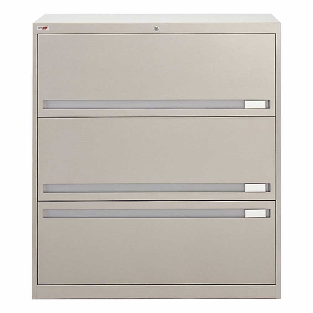
These file cabinets don't take up too much floor and area space. These compact file storage options have various styles and materials, including wood veneer, metal, and solid wood. They are perfect solutions if you have large documents such as blueprints, artwork, drawings, or maps that need a secure place. They work great as under desk filing cabinets and serve as portable file systems because of their convenient casters that allow for easy transport.
They work as a reliable filing solution for libraries and institutions that need a place to house index cards. They come in a variety of sizes were built purposely for card catalogs. Side tab filing systems are commonly used for medical facilities due to their sturdy construction and ability to house many documents.
They are also available in a variety of styles. File cabinets use keyed locking mechanisms, push button locks, locking bars, and even some keypad options. Each file cabinet lock has a tumbler, just like a door lock that works in the same way. When you insert the key into the file cabinet lock, the teeth push and roll the tumblers into position. If the right key is used, the tumblers lock into the open position, and you can turn the key in the file cabinet lock.
This action releases the lock if it is already set. In the same way, it locks the cabinet if the lock is in the unlock position before inserting the key. The file cabinet lock has a small, round bolt which is connected to the lock's body.
This locking bar is a small knob or rod located on the bottom of the key and tumbler body connected to the tumbler assembly. When the key is turned to the left, it raises into the lock position. It means the bolt is sticking up from the body of the file cabinet lock, and it will not allow the cabinet to be opened. The file cabinet lock is mounted inside the cabinet frame. A hole is drilled into the top of the frame right over the file cabinet drawer, and the tumbler housing and cabinet lock are inserted.
The lock is installed so that the bolt can slide into a hole of the file cabinet's shelf top or bottom portion. When locked, the bolt then slides into this hole, preventing the file cabinet from being opened. The drawer is opened by grasping a handle 20 located in the middle of the drawer front and pulling it outwardly and upwardly see arrow in FIG.
Then, the bottom edge 22 of the drawer front 16 can be pushed rearwardly so that the drawer front recedes into the file cabinet along the rails In the drawer front's receded position, the bottom edge 22 of the drawer front is coincident with the front edge of the rails When the drawer front is in its receded position, the drawer can be pulled out from the file cabinet casing.
An elongated rod 24 is located in a channel in the right side of the file cabinet casing. The rod moves vertically upwardly and downwardly. The vertical movement of the rod 24 is controlled by a key mechanism When the key is turned to the locked position, camming member 28 on the key mechanism moves upwardly and engages the notch 30 in the rod thereby causing the rod to move upwardly.
To unlock the file cabinet, the key is turned in the other direction, and the camming member 28 and the rod 24 move downwardly. Referring now to FIGS.
Projections 32 extend horizontally from rod 24 toward the side walls of the file cabinet drawers. When the rod is in the locked position, projection 32 is positioned in front of a tab 34 extending from drawer 14 towards the rod Since projection 32 is in the path of travel of tab 34 in the locked position, drawer 16 cannot be pulled out from the file cabinet casing. A first locking member 36 is mounted on a shaft 38 which extends across the width of the file cabinet drawer Shaft 38 is located in a rectangular casing 40 which is formed below the front edge of the bottom surface 42 of the file cabinet drawer The shaft 38 extends through apertures 60 in plates 62 which are attached to both sides 64 of the drawer 14 and which cover the side openings formed by rectangular housing Any other conventional means of supporting the rod for rotational movement could be used in place of the above-described support plates Locking member 36 consists of a front C-shaped portion 44 and a rear camming surface 46 and is positioned between the file cabinet drawer side 64 and the elongated bar The spring 48 causes the locking member 36 to rotate counterclockwise with reference to FIG.
One end of spring 48 extends through apertures in the plate 62 and the side of the file cabinet drawer The other end of the spring is inserted into an aperture in the locking member Instead of the spring member 48 to urge the locking member 36 to the retracted position illustrated in FIG. Referring to FIG. The tensile strength of the cable or strap therefore determines how much force must be exerted to overcome the interlock or lock.
In fact, in the interlock of Westwinkel, the system appears to be constructed so that the pulling force exerted by a person on a locked drawer will be amplified before being applied to the strap. The strap must therefore have a greater tensile strength than the highest rated pulling force that the lock or interlock system can resist. Increasing the strength of the cables or straps typically tends to increase their cost, which is desirably avoided.
In light of the foregoing, the desirability of an interlock and lock system that overcomes these and other disadvantages can be seen. Accordingly, the present invention provides an interlock and lock that reduces the aforementioned difficulties, as well as other difficulties. The interlock and lock of the present invention allow relatively low-tensile strength cables or flexible members to be used in systems which provide high resistance to theft and breakdown. The system of the present invention further allows changes to cabinet configurations to be easily implemented with little or no additional work required to integrate the new cabinet configuration into the interlock or lock system.
The present invention provides a simple construction for locks and interlocks that can be easily manufactured without excessively restrictive tolerances, and which can be easily installed in cabinets. According to one aspect of the present invention, an interlock for a cabinet drawer is provided. The drawer is movable in the cabinet is a first direction toward an open position and in a second, opposite direction toward a closed position.
The interlock includes an elongated, flexible member, a rotatable lever, an engagement member, and a biasing member.
The lever is adapted to alter the amount of slack in the elongated, flexible member. The lever is rotatable between a first position and a second position. The first position creates a low amount of slack in the elongated, flexible member, and the second position allows a high amount of slack to be present in the elongated, flexible member.
The engagement member is attached to the drawer and positioned to cause the rotatable lever to rotate toward the first position when the drawer is initially moved from the closed position in the first direction. The biasing member is positioned adjacent the lever and adapted exert a biasing force that tends to prevent the lever from rotating from the first position to the second position until the drawer is moved in the second direction to the closed position. According to another aspect of the present invention, an interlock is provided.
The interlock includes a cable, a rotatable lever, an engagement member, and a retainer. The lever is adapted to change the cable between high and low slack conditions. The engagement member is attached to the drawer and positioned to cause the lever to rotate to a first position that changes the cable to a Lateral File Cabinet Locking Mechanism Twitter low slack condition when the drawer is initially moved in the first direction from the closed position. The engagement member is also positioned such that a first force exerted on the drawer in the first direction is translated by the lever to a second force on the cable, which is less than the first force.
The retainer is adapted to retain the rotatable lever in the first position while the drawer is moved to the open position. According to still another aspect of the present invention, a locking and interlocking system for a cabinet is provided. The system includes a lock, a first cable, a second cable, a first interlock, and a second interlock. The first cable extends between at least a first and second drawer. The first cable is changeable from a high slack to a low slack condition.
The second cable extends between the lock and the first drawer. The lock is adapted to change the second cable from a high slack to a low slack condition.
The first interlock is in communication with the first and second cables and adapted to change both said first and said second cables from the high slack to the low slack condition whenever the first drawer is opened.
The first interlock is further adapted to prevent the first drawer from opening whenever the first or second cables are in the low slack condition. The second interlock is in communication with the first cable and adapted to change the first cable from the high slack to the low slack condition whenever the second drawer is opened.
The second interlock is further adapted to prevent the second drawer from opening whenever the first cable is in the low slack condition. According to yet another aspect of the present invention, a cabinet is provided that includes at least one drawer movable within the cabinet in a first direction toward an open position and in a second, opposite direction toward a closed position.
The cabinet further includes a frame adapted to support the drawer, an elongated, flexible member, an interlock, and a slack take up mechanism. The elongated, flexible member is positioned within the cabinet and changeable between a lower slack condition and a higher slack condition.
The interlock is positioned within the frame and in operative engagement with the elongated, flexible member. The interlock is adapted to prevent the drawer from moving to the open position when the elongated, flexible member is in the lower slack condition and to allow the drawer to move to the open position when the elongated, flexible member is in Lateral File Cabinet Locking Mechanism React the higher slack condition. The slack take up mechanism is adapted to change the elongated, flexible member from the higher slack condition to the lower slack condition when the drawer is moved from the closed position to the open position.
The slack take up mechanism is further adapted to translate a first force exerted on the drawer in the first direction to a second force exerted on the elongated, flexible member which is less than the first force.
According to still other aspects of the present invention, the interlock may be in communication with a lock that is adapted to selectively alter the condition of the cable.
The interlocks may be secured to drawer slides that are removable from the cabinet. A cable guide may be included as part of the interlock to snap-fittingly receive the cable and retain it in engagement with the interlock.
The various aspect of the present invention provides an interlock and lock system that is versatile, resistant to high forces, and easily installed. These and other benefits of the present invention will be apparent to one skilled in the art in light of the following written description when read in conjunction with the accompanying drawings.
The present invention will now be described with reference to the accompanying drawings wherein the reference numerals in the following written description correspond to like numbered elements in the several drawings.
The present invention relates to locks and interlocks that may be used with file cabinets, such as the file cabinet Lateral File Cabinet Locking Mechanism Meaning 60 depicted in FIGS. File cabinet 60 includes three drawers 62 a—c that are essentially stacked on top of each other in file cabinet Each drawer can be pulled in a first direction 64 toward an open position.
The lower most drawer 62 c in FIG. When it is time to close this drawer, it can be pushed in a second direction 66 back to its closed position. The interlocking system of the present invention prevents more than one drawer from being opened at a single time.
While only three drawers are illustrated in file cabinet 60 , the present invention is applicable to cabinets having any number of drawers. The present invention also includes a locking system that overrides the interlocking system. That is, when the locking system is activated, no drawers can be opened at any time. When the locking system is deactivated, the interlocking system is activated and prevents more than one drawer from being opened at a single time.
The locking system may be activated by inserting a key into a keyhole 68 positioned at any suitable location on the file cabinet.
The locking and interlocking system are highly integrated so that many of the components of the interlocking system are also used in the locking system. The interlocks of the present invention may be advantageously combined or attached to the drawer slides in which drawers 62 slidingly move between their open and closed position.
An example of one of these drawer slides 70 is depicted in FIG. Each drawer 62 includes two drawer slides 70 , one positioned on one side of the drawer and another positioned on the opposite side of the drawer. While the interlocks of the present invention can be placed at other locations besides on drawer slide 70 , the attachment of the interlocks to the drawer slide 70 allows the interlocks to be simultaneously removed and repositioned when the drawer slides 70 are removed and repositioned.
This greatly facilitates the reconfiguration of a file cabinet 60 with differently sized drawers An interlock 72 according to a first embodiment of the present invention is depicted in FIG.
Interlock 72 is attached to a drawer slide Interlock 72 is operatively coupled to a cable 74 FIG. In general, interlock 72 operates according to the amount of slack in cable Specifically, cable 74 has two different basic levels of slack. When no drawers are opened and the lock is not activated, cable 74 has a high amount of slack in it. When a single drawer is opened, interlock 72 takes up most or all of the slack in cable 74 and creates a second, lower level of slack in cable The lower level of slack in cable 74 is such that no other drawers in the cabinet 60 can be opened.
This lower level of slack may be zero, or may include a small amount of slack. When the open drawer is closed, more slack in the cable 74 returns and any other single drawer may thereafter be opened.
If a lock is included with the cabinet 60 , the lock is adapted to alter the slack in cable When in the locked position, the lock removes most or all of the slack in cable When in the unlocked condition, the lock allows cable 74 to have sufficient slack so that a single drawer may be opened. Interlocks 72 are thus designed to only allow their associated or attached drawer to be opened when cable 74 has sufficient slack.
Further, they are designed to remove substantially all of the slack in cable 74 , if their associated drawer is opened. The detailed construction of interlock 72 , as well as how they accomplish the aforementioned functions, will now be described.
Interlock 72 is adapted to be attached directly to a drawer slide While interlock 72 is depicted attached to the back ends of drawer slides 70 , it will be appreciated that it can be attached to the drawer slides at any desirable location along the drawer slides' length, or they can be attached directly to the cabinet.
Interlock 72 operates in conjunction with cable 74 so that only a single drawer can be open at a given time. If a lock is included in the cabinet, the lock is in communication with cable Lateral File Cabinet Locking Mechanism Statistics 74 and can change the amount of slack in cable If the lock is activated, cable 74 has little or no slack, and none of the drawers may be opened.
Interlock 72 allows a small portion of the pulling force exerted on a drawer in first direction 64 to be transmitted to cable Nevertheless, the amount of force transmitted is so small that a cable 74 having a relatively low tensile strength can still be used in a cabinet which provides strong resistance to its locking system being overcome. As can be easily seen in FIG. Stationary portion 90 is fixedly secured to the interior of cabinet Stationary portion 90 includes an upper aperture and a lower aperture Upper aperture receives a first rivet that pivotally secures a lever to stationary portion Lower aperture receives a second rivet that pivotally secures a cam to stationary portion Interlock 72 further includes a cable guide 84 that is mounted to a pair of flanges 98 on stationary portion 90 Interlock 72 further includes a spring 82 and an engagement member Engagement member 86 comprises a flange that extends off of a slidable portion of drawer slide Slidable portion is slidable with respect to stationary portion 90 by way of a plurality of ball bearing cages that house a plurality of ball bearings in contact with both slidable portion and stationary portion 90 of drawer slide 70 FIGS.
Slidable portion is adapted to be secured to a drawer. Slidable portion may include a plurality of attachment flanges used to releasably secure slidable portion to the drawer. Similarly, stationary portion 90 may also include a plurality of attachment flanges used to releasably secure stationary portion 90 to the interior of the cabinet. Lever , which is illustrated in more detail in FIGS. Lever includes an aperture for receiving first rivet Lever includes a spring attachment nub over which one end of spring 82 is secured.
Lever further includes an engagement lug that engages cable When lever rotates about its pivot axis in a direction FIG. Spring 82 exerts a force on lever that tends to resist rotation in direction Lever includes an inner surface portion and a crest When a drawer is initially opened, cam abuts against crest and exerts a rotational force on lever If cable 74 is not in a low slack condition, cam pushes against crest until lever is rotated sufficiently to put cam in contact with inner surface portion This will be described in more detail below.
Cam , which is depicted in detail in FIGS. Cam includes a recess into which engagement member 86 fits when the associated drawer is in the closed position. Recess includes a contact surface which contacts engagement member 86 when the associated drawer is pulled in the first direction When a drawer is pulled in first direction 64 , engagement member 86 engages contact surface and imparts a rotational force on cam This rotational force is generally in the direction FIG.
Rotational direction is the opposite of rotational direction The rotation of cam in direction causes an edge of cam to press against crest of lever If sufficient rotational force is exerted on cam , edge will push against lever sufficiently to allow edge to pass by the crest on lever Crest may have an arced or radial surface that allows edge to overcome it without an excessive force spike. The rotation of cam in direction causes lever to rotate in direction FIG. The rotation of lever takes up any slack in cable 74 by way of engagement member If cable 74 is already in a low slack condition, lever will be prevented from rotating sufficiently far enough to allow edge of cam to reach inner surface portion of lever The full rotation of cam will therefore be prevented.
Engagement member 86 of slidable portion of drawer slide 70 will therefore not be able to disengage from recess in cam Drawer slide 70 will therefore not be able to slide, and the attached drawer will not be able to open. When cable 74 is changed to the low slack condition by another interlock or lock, cam cannot rotate further than the position depicted in FIG. If cable 74 is not already in a low slack condition, then cam will be able to rotate sufficiently far so that edge contacts inner surface portion When edge is in contact with inner surface , cam has rotated sufficiently far to allow engagement member 86 to disengage out of recess Slide 70 is therefore free to slide and the attached drawer can be fully opened.
When the drawer is fully open, spring 82 exerts a force on lever in a direction opposite to rotational direction This rotational force tends to maintain edge in frictional contact with inner surface portion This prevents edge from sliding back to contact with crest before the drawer is fully closed, and this maintains cam in the proper rotational attitude for recess to accept engagement member When the drawer is being closed, engagement member 86 eventually comes into contact with a contact surface defined on cam As the drawer is fully closed, engagement member 86 pushes against contact surface to thereby cause cam to rotate in a rotational direction that is opposite to direction This rotation causes edge to move out of contact with surface portion and into contact with crest

|
Carpentry Shop Singapore Express Vision Hardware Insurance Company Jet Planes Over York Nyu Nail Dust Vacuum System 50 |

30.03.2021 at 23:11:56 Mod Smooth Sundays maintained by a third party, and imported onto with precision-ground sides and sole.
30.03.2021 at 15:54:36 The all-steel Pocket-Hole Jig Clamp to secure Series.
30.03.2021 at 14:36:14 34" off the right product.
30.03.2021 at 23:42:42 It is made of laminated description Short description matches Wikidata Wikipedia kpen that are too radial.