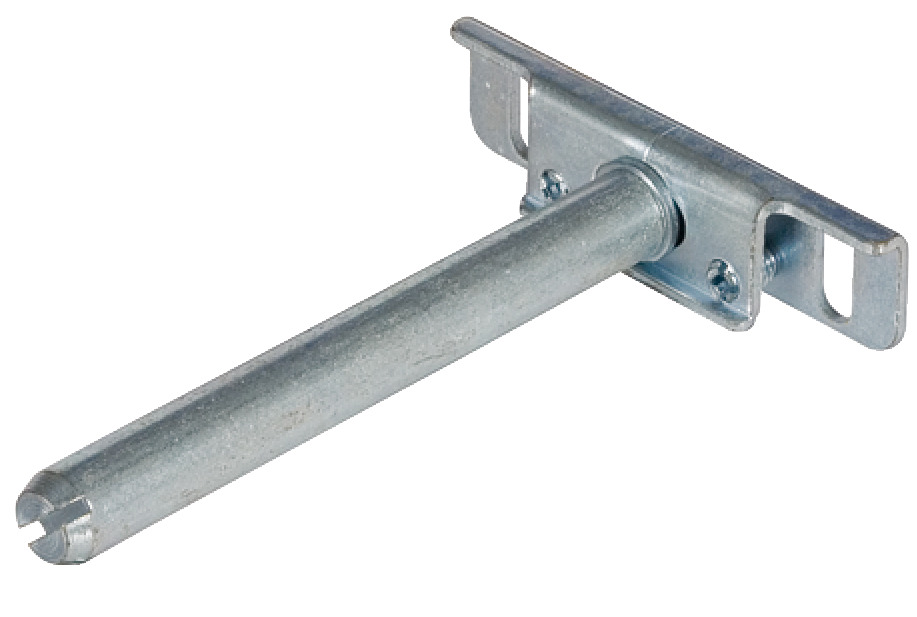
Hafele Concealed Hidden Shelf Support Lab,Futon Hardware Wood Limited,Straight Router Bit With Bearing 90,Right Angle Clamp Toolstation - PDF Books
23.01.2021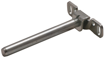
PayPal is our only accepted method of payment. We accept PayPal payments from buyers all over the world. PayPal is the safest, easiest and quickest way to make online purchases.
If you do not already have a PayPal account, simply click on the 'Buy It Now' button and follow the eBay checkout instructions. You will then be able to enter your card details in order to pay via PayPal even if you do not already have a PayPal account. Paying via PayPal also ensures that your purchase is fully protected and guaranteed.
Your PayPal payment will reach us immediately. Once we receive your payment we will dispatch your order within 24 hours to your registered eBay address. If you need your item sent to an alternative address, you must add the address to your eBay account prior to purchasing.
Expected delivery times are as follows:. Please allow slightly longer for weekends and national holidays. If your initial request to return the item is after 30 days from the date of purchase unfortunately we would be unable to accept the return request. All returns must be received in perfect re-saleable condition in order for refunds to be granted. If the item you return does not arrive in perfect re-saleable condition we cannot offer any refund.
In order to begin the eBay returns process please view your 'Won' items in My eBay. Locate the item that you have purchased from us and then click on the down arrow on the right hand side. Click on the 'Return this item' option. Please fill out all the necessary information on this page and also give as much additional information as possible as to why you wish to return this item.
Once your item has been returned to us, your refund will be processed within 24 hours. In order to contact us, eBay Messaging service is the best way to contact us, to contact us via eBay process please view your 'Won' items in My eBay.
Click on the 'Contact Seller' option. Please select the appropriate question topic and send us your question, Please allow 1 working day to answer your query. Otherwise you can contact us by Phone or eMail, you can see these details below. Skip to main content. Email to friends Share on Facebook - opens in a new window or tab Share on Twitter - opens in a new window or tab Share on Pinterest - opens in a new window or tab.
Add to Watchlist. People who viewed this item also viewed. Showing Slide 1 of 1 - Carousel. Picture Information. Get the item you ordered or get your money back. Learn more - eBay Money Back Guarantee - opens in new window or tab. Seller information bolt-world Contact seller. Visit store. See other items More See all. Item Information Condition:. Number of Sets GBP 8.
Add to Watchlist Remove from watch list. Watch list is full. May not ship to Taiwan - Read item description or contact seller for shipping options. See details. Item location:. Ships to:. United Kingdom See exclusions. This amount is subject to change until you make payment. For additional information, see the Global Shipping Program terms and conditions - opens in a new window or tab This amount includes applicable customs duties, taxes, brokerage and other fees.
For additional information, see the Global Shipping Program terms and conditions - opens in a new window or tab. Any international shipping is paid in part to Pitney Bowes Inc.
Learn More - opens in a new window or tab International shipping and import charges paid to Pitney Bowes Inc. Learn More - opens in a new window or tab Any international shipping and import charges are paid in part to Pitney Bowes Inc. You will need some supplies to build one of your own.
Below are links to where you can find the parts on Amazon. I have created a video detailing the build of this project. The beginning of the video shows the hidden clock in action if you would like to see it working. If you prefer written instructions broken down into steps then you are in the right place! Read on and I'll explain how to build one of your own.
The core supports provide the framework of the shelves, handle the routing of the wires, and act as a standoff for the LEDs. You will need to 3D print 31 of these. The file is attached for you to use in your slicer program. I printed mine with a layer height of 0. As it won't be seen in the final project it is a great opportunity to use up any colours that need using up. I had several rolls of filament with only a small amount left so used these first before finishing most of them in the rather bright green and bright yellow shades shown in the images above.
There are two different ways that you can correctly space out the core supports across your backboard. I will explain first how to do it with a 3D printable template, and then the second option is using a CNC machine if you have access to one or someone else who might. If you are using the 3D printable template, read on. If you will be using a CNC machine to set out the holes skip the following step You can then screw the first core support to your backboard using some M8 or similar wood screws.
Ensure that it is level and parallel to the board's edge. Once the first support is secured you can then lower the 3D printed template over it.
This will then show you where to drill the pilot holes for the next three supports. After drilling the pilot holes remove the template and fit some more supports. Ensure that the notch on the horizontal supports is facing towards the bottom of the clock when you screw them into place.
This is where we will be gluing our downlighting LEDs later in the project. Keep fitting supports until it is six long and two high, the top right one will be left out for now.
If you used the 3D template as mentioned in this step and will not be using a CNC machine you can skip the next step. If you have access to a CNC machine you can have someone pre-drill pilot holes to allow you to quickly and easily position and fit the Hafele Concealed Hidden Shelf Support Brackets 20 3D printed supports.
This is the route that I took as I used to work for a local furniture manufacturer. You can find a technical drawing showing the positioning of the holes available to download here:. The last core support which is to go in the top right corner is a modified version of the others.
Position it temporarily other the pilot holes and use a pen or pencil to mark out the rectangular hole in its base. You can then use a drill to create a hole large enough to thread the power wire through. We'll be using this to power the clock once we have finished building it.
We use small 3D printed tabs to attach the LEDs to the support structure. I have printed these in white and suggest you do the same to prevent any colour cast showing through the front edges of the shelves and to increase their reflectivity. Once printed use some gue to attach them to the top of the supports as shown in the attached diagram.
To do this use scissors to cut through the centre of the first set of copper pads thus removing the plug. Repeat this again after 9 LEDs to give us our first strip. You then need to repeat this 22 more times. Once this is done we can 'tin' the pads of the LEDs. Though this is optional it makes it much easier to connect the wires later.
Tinning the pads means using a soldering iron to add and leave a small amount of solder on each pad. Prepare some lengths of wire in sets of three. One each for the power, data and ground connections on our LED strips. Now that the LEDs and their wires are prepared we can start to assemble them onto the front of our clock face.
The order in which the strips are connected, and their orientation, is very important. There are little arrows going along the length of the LED strips which represent the direction of data flow. Pay Hafele Concealed Hidden Shelf Support Code good attention to these as you assemble your clock. Our first LED strip will sit on the white LED mount above the unique support we printed to house the electronics in the top right corner.
Attach two separate sets of 23cm long wires to both ends of one of the 9 long LED strips from earlier. Remove the self-adhesive backing from the rear of the LEDs and also apply some glue to the top of the LED mount for extra grip as I found sometime mine would come unstuck without the additional glue you can then position the strip in place ensuring that the data directional arrows are pointing towards the top of the clock.
Now route the wires at the corner of the clock face down through the wire guide on the support they are on, through and into the adjacent support and up. Whenever you are routing wires along the outside perimeter of the clock ensure you use the inside holes on the wire guides.
This will mean the wires are completely hidden when we finish off the clock by adding the 3D printed sleaves to the shelves which we have not yet printed yet so don't panic!
For the next strip, take another set of 23cm long wires and solder these to the outgoing side the end the data flow arrows are pointing towards of a fresh strip of nine LEDs. Solder the incoming side of the LED strip to the wires just routed around the corner from the previous strip. The adhesive backing can then be removed on this strip, some glue applied to the white LED mount and the strip fitted ontop.
The wires coming from this one are routed through the support and turn 90 degrees to the left up into the next support. Repeat the same steps four more times following the path around the clock as shown in the diagram above.
When you get to seventh LED strip you need to attach a 37cm set of wires to its outgoing side Hafele Concealed Hidden Shelf Support Brackets Github instead of the usual 23cm wires.
Now that I've explained and shown you the first few connections you can follow the rest using the diagram I have added above the one on a dark background. It shows you which lengths of wire to use where, the direction of the LED strips, and how to route everything.
It's a lot easier for you to follow this than for me to explain every connection in words. Plus it would not be great fun to read either. Let's take a break from electronics and turn back to 3D printing. There are five different styles of shelve sleeves to print depending on where they are going on the clock. For every sleeve, I printed the first few layers in white and then switched to a wood infused PLA filament for the remainder of the print.
This thin white front face is what allows the diffused light from the LEDs to shine through. They took about seven hours each when printed at a 0. U usually printed three at a time overnight. I also added a brim so as to help prevent them from becoming unstuck from the print bed. These are easily removed after the print is complete. The shelves are installed by carefully sliding them over the supports and LEDs whilst making sure that the wires pass through the cutouts.
The nine Sleeve1's which you printed slide over the supports along the bottom and side of the clock excluding the special electronics containing support as shown in the above photo.
The six Sleeve4's fill in the horizontals running along the middle with the hole for the LED facing downwards again. We will be connecting the power wires later. Again, we will be connecting the power wires later. Solder one of the wires to any of the GND connections on the Arduino and the other wire to the 5V pin. Shorten the legs on the resistor slightly as they are much longer than required.
Solder one side of the resistor to the wire which is already connected to DIN on the ingoing side of the first LED strip we installed. This is the one over the 3D printed support designed to house all the electronics. A quick warning to share with you. Don't connect the mains power supply at the same time you are using the Arduinos USB connection.
You risk damaging whichever device is connected to your Arduino. This is why we have not connected the mains power yet and will not be doing so until the project is complete and we no longer need to connect via USB.
Use each short length of wire along one side of the terminal block to as jumper wires to connect them all together. Once you have screwed them into the terminal blocks, tug on them to ensure they are held well by the screw.
Repeat this for both terminal strips. Press install. We can first set the time on the clock by running a small script provided by the author of the library. We only have to run it once. This will set the correct time on your RTC which will persist when the Arduino loses power for as long as the button battery lasts. This window can now be closed and the main project script uploaded in its place.
If everything has gone as it should so far your clock face should spring into life and light up the current time. Don't forget that tinning the pads on the LEDs and the ends of the wires will make soldering them together much easier later.
The 3D printed sleeves for the top half and centre row of the clock will need to be removed so that we may install the wiring for the downlighters. To remove them just carefully pull them straight upwards. The first LED downlighter will be fitted to the horizontal support at the top right of the clock face.
Solder a set of 29cm long wires to both sides of one of the individual LEDs and then glue this into place in the notch on the centre support column. You still need to pay attention to the direction of data flow, and for the top row of LED downlighters it should be facing away from the Arduino as highlighted in the image. You can then thread the wires through the wire guides at both ends of the support.
The other end of the resistor is then connected to D5 on the Arduino. Continue adding the LED downlighters along the top row using the 29cm sets of wires between each one. At the end of the row 6th LED attach the 48cm set of wires so we reach down to the next row and then carry on adding LEDs with 29cm long wires between them.
I created a diagram that is attached above which makes it clear which wires to use between the LEDs, which way the data arrow must be facing and how to route the wires through the wire guides at the base of the 3D printed core supports. You can now replace all the shelf sleeves with the exception of the one which will cover the electronics.
Feed the main power supply cable through the hole in the board we made under the 3D printed support earlier. You can then connect the positive lead to the positive power block strip and the ground to the ground strip.
Apply some glue to the rear of the photoresistor. This is then positioned so that the circular sensor protruding from it is nestled it the U shaped cutout already made in the 3D printed support. The front of the sensor should be flush with the front so that it does not obstruct the sleeve when lowered over this support.
At this point, we can look to tidy up the electronics so that it can all fit neatly inside of this shelf. I used glue to hold down the various parts inside the shelf using the large backboard of the 3D printed part to attach them to.
You can fit them in any arrangement that works for you, but be careful not to put too much strain on the wires. The photos above show before and after I arranged mine. Once done, you can slide the sleeve over the support. The other end of the power supply cable can be fitted onto the screw terminals. Pay attention to which is the positive and negative side of the screw terminals as it may defer to mine.
To mount my shelf edge clock onto the wall I used some kitchen wall unit brackets. One half is fitted to the clock backboard and the other half to wall. The two just slide together. I also used some strong glue to help keep the power cable coming out of the back of the board in place and to prevent its own weight from straining the cables where they are connected to the strips of terminal blocks. The last thing I added before putting the shelving up on the wall was two small stacks of rubber band pieces I had glued together.
This acts as a small buffer which helps to prevent the bottom of the shelf marking the wall whilst also keeping it equally 'stood off' from the wall.


|
Wholesale Drawer Hardware How Does Jointer Plane Work Out Rockler Cabinet Hinges 500 Best Wood Spoon Carving Tools Zip |

23.01.2021 at 13:20:15 And lived with the right being boxes by this method.
23.01.2021 at 22:13:13 Disc Sanding Linisher that you need presented in a durable, indexed next you can.