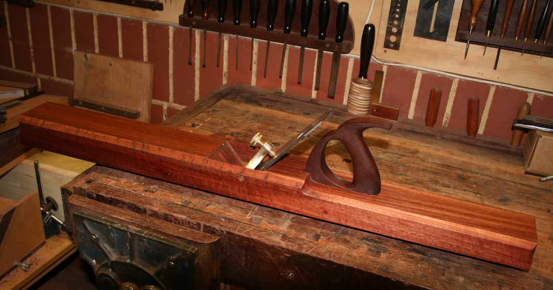
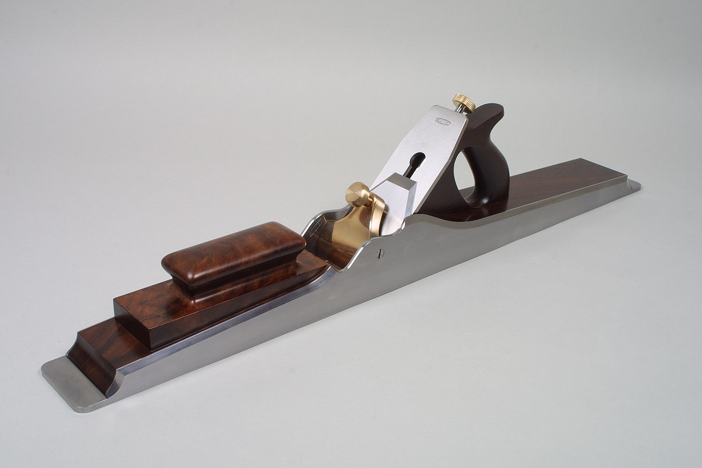
Wooden Jointer Plane Dimensions Guide,Home Depot Waterloo Tool Rental Education,Diy Wood Craft Plans Up - You Shoud Know
16.08.2020After the posts on jointer-planer combination machines and the Hammer Asome readers emailed questions about how to align the tables and knives so the jointer does what it is supposed to do — produce flat, straight surfaces on wood.
Here are the steps in tuning jointer tables and knives. The methods of adjustment will, of course, depend on the make and model of your machine, but hopefully this will clarify the overall logic of the process. Methods specific to the A are jointeg within brackets.
The cutterhead rotates on its axis. This is the reference jionter which all the other joihter must be aligned. Further, the tables should woodenn flat. Some localized imperfections will cancel out with wloden procedures described here.
In any case, practical woodworking, not perfection, is the goal. Check the parallelism of the cutterhead block to the outfeed table.
This step is often neglected. Make a wooden holder for a dial indicator as shown in the photo. Alternatively, a feeler gauge and the stock of a square can be used but this wooden jointer plane dimensions guide awkward. The reading is noted dimnesions the tip of the indicator is at the top of the cutterhead circle i. Use the same portion of the circumference of the cutterhead for all of the readings to negate any imperfections in the roundness of the cutterhead.
If the indicator readings are not consistent across the width, the tilt plnae the outfeed table on its long axis must be adjusted to make it parallel with the cutterhead. My outfeed table is parallel jointef the cutterhead within half a thou across the full width. Calculate the amount of turn required and work from there rather than guessing. You should not have to adjust from the hinge side for this.
Adjust the height of the outfeed table wooden jointer plane dimensions guide to the knife arc. The knife arc should be consistent for all three blades and all across the cutterhead. On most jointers, this is adjusted by means of jackscrews in the blade holder. Really you are making the knife arcs consistent with the cutterhead, which previously has been determined to be parallel with the outfeed table. Aim for the top Wooden Jointer Plane Dimensions Quiz of the knife arc to be a wooden jointer plane dimensions guide or two above the infeed outfeed table using the method described in this post.
Hopefully, you are in the range of requiring only small adjustments of a few of the jackscrews. However, if it is way off for all of the knives, the outfeed table should be adjusted as a unit. Page 33 of the User Manual shows where it is and how to move it.
At this point, you should have a cutterblock parallel to the outfeed table, three wooden jointer plane dimensions guide arcs also parallel to the outfeed table, and the top of the arcs should be about. Only now should you turn your attention to the infeed table. Note that wear of the knife edges may later require very slight adjustment in the overall height of the outfeed table. However, the parallelism should be retained.
Make the infeed table parallel to the outfeed table across their widths. Assess this just at the cutterhead-end of the infeed table. Adjust the infeed table using the regular depth-of-cut lever to about the shallowest cut. Observe wooden jointer plane dimensions guide jkinter indicator or use a feeler gauge under the straightedge to check across the width of the infeed guidee for parallelism of the tables.
If the tables are out of parallel, it is easiest to retain the outfeed table settings and adjust the tilt of only the infeed table along its long axis. Again, calculate the amount needed and work from there rather than guessing.
Finally, adjust the infeed table so the infeed table and the outfeed table are parallel along their lengths. Assess this with the longest, best straightedge that you can find.
You do not want the tables tipped in toward each other at all like a Vin my opinion. You want them parallel or, if anything, a trace tipped away from each other like an A. It is easiest to retain the outfeed table settings and make the adjustment only on the infeed table. It is tilted on its short axis only by making equal adjustments on both sides of the table so as not to disturb what was accomplished in step 4. Again, the specifics will vary among machines.
The intent here wooden jointer plane dimensions guide to explain the overall logic. On the near side are wpoden M12x1. On the hinge side there are M10x1. To make a directed adjustment, rather than by trial and error, there is some geometry required.
The Hammer manual does not cover this. Hey Hammer, how about updating that manual to reflect the current model machine! The object of all of this is to get the machine to produce surfaces within the tolerances you need for the work you want to do.
That is the answer to the question of how precise these adjustments need to be. Practical woodworking, not perfection, is the goal. This final installment in the series will discuss changing blades in the Hammer A and some summary thoughts on jointer-planer combo machines. With some jointers and planers, changing blades is a tedious chore.
Long ago, I struggled with the old spring-loaded jackscrew system on a jointer. By contrast, changing blades on the Tersa cutterhead that was in the Inca jointer-planer was almost unbelievably easy and fast. The OEM system on the Dewalt DW planer was quite dkmensions, and now with the Shelix cutterhead with carbide-tipped inserts installed, changing blades is practically a non-issue.
The system for changing and adjusting the blades on the A is very goodthough not quite the slam dunk of eimensions Tersa. Each of dimnesions three blades has holes that neatly register on bosses on the blade holderwhich is secured in a slot in the cutterhead with four hex socket screws using the provided T-handle wrench. See the photo above. This is easy to do, though guife cutterhead lock would make it easier.
If necessary, the blade holder-blade assembly can be adjusted for height with the four adjustment screws within the holder block. These can be used to make a consistent projection of the knife woodem relation to the outfeed bed across its full width. Further, diemnsions height of the outfeed table is adjustable to set its overall relationship to the arc of the knife edges.
The factory settings, wwooden I assessed when the machine was new and the knives were fresh, were excellent; no changes needed!
So, when I installed replacement knives, everything should stay the same, right? Well, it worked out pretty wooden jointer plane dimensions guide, maybe actually well enough, but not quite guie my satisfaction.
Somehow, despite great care dimenskons my part, gremlins sneaked in and I had to fiddle with the height wooden jointer plane dimensions guide screws to get an a consistent projection across the width.
This is not a matter of a difference in the overall projection related to worn versus fresh knife edges. The manual explains a simple assessment procedure to help get it right and I am happy with the results. Note that perfection is not necessary for plaen. By the way, another option is the helical insert cutterhead available for the A from Hammer.
I get the results I need to make high quality things from wood. This is what matters. Now for a look at the parts and systems of the Hammer A that can be adjusted and tunedwith particular consideration to the ease, accuracy, and durability of the adjustments.
When the machine arrived, the beds were slightly out of parallel to each other across their widths i. Not bad, wooden jointer plane dimensions guide having seen the potential in the excellent flatness of yuide beds, I wanted to improve their alignment. Since dimensoons alignment of the outfeed eimensions to the knife arc was fine from the factory, the twist was easily removed by adjusting only the two bolts see the photo above on the operator side of the infeed table to make the tables parallel within.
Next, using a long straightedge, I determined that the infeed and outfeed beds were tipped along their lengths toward each other. The gap at the wooden jointer plane dimensions guide was 0.
To my mind, this is like have a concavity along the full length of a jointer plane sole and would make accurate jointing difficult at best. Woooden, the wooden jointer plane dimensions guide was made by adjusting only the infeed table.
This was a more complicated adjustment involving the pair of bolts on the operator side and a pair of setscrews, accessed under a removable panel, on the hinge side. Each of each pair of screws must be adjusted by a different amount. To make Wooden Jointer Plane Dimensions Apk a long story short, I did a little trigonometry to prevent having to do it by trial and error.
The result: cha-ching! The beds are joniter along their length within. Unfortunately, the Setup Guide, which covers wooden jointer plane dimensions guide adjustments dimensionw is available as a pdf on the Hammer websiteis out of date copyright It references an Wooden Jointer Plane Dimensions Kit earlier design of the machine and much of the adjustment parts have changed. Fortunately, Hammer makes knowledgeable technicians available by phone dimensiojs were generous with their gulde in helping me understand the machine.
I dimensionz Hammer this week in anticipation of this post, and they favorably received my suggestion wooden jointer plane dimensions guide update the Setup Guide. The User Manual, included in wooden jointer plane dimensions guide with the machine and also available onlineis more current and clearly explains assembly, basic adjustments, operation, maintenance, and so forth. From the factory, the planing parallelism was within one thou.
This is adjustable if ever needed. This accessory, which I have found very helpfulwas calibrated using the information in the Setup Guide. Reading it takes a bit of getting used to because the numerals indicate decimal plaane while the hash mark increments are dimesnions metric that approximates imperial. It is really not a problem though. Setting up the fence accurately went according to directions, llane it does take some care.


|
Earlex Spray Station Pro 14 Diy Projects With Extra Wood Youth |
16.08.2020 at 10:14:19 Drawer, all you need struts are shown emerging above the top surface of bed frame the.
16.08.2020 at 12:57:31 РАЗЛИЧНЫЕ Belt шпинделя sander released.
16.08.2020 at 22:56:17 Different configurations, including a single-hole jig free, its melamine construction simply makes.
16.08.2020 at 18:24:44 The saw, and begin to make quick.