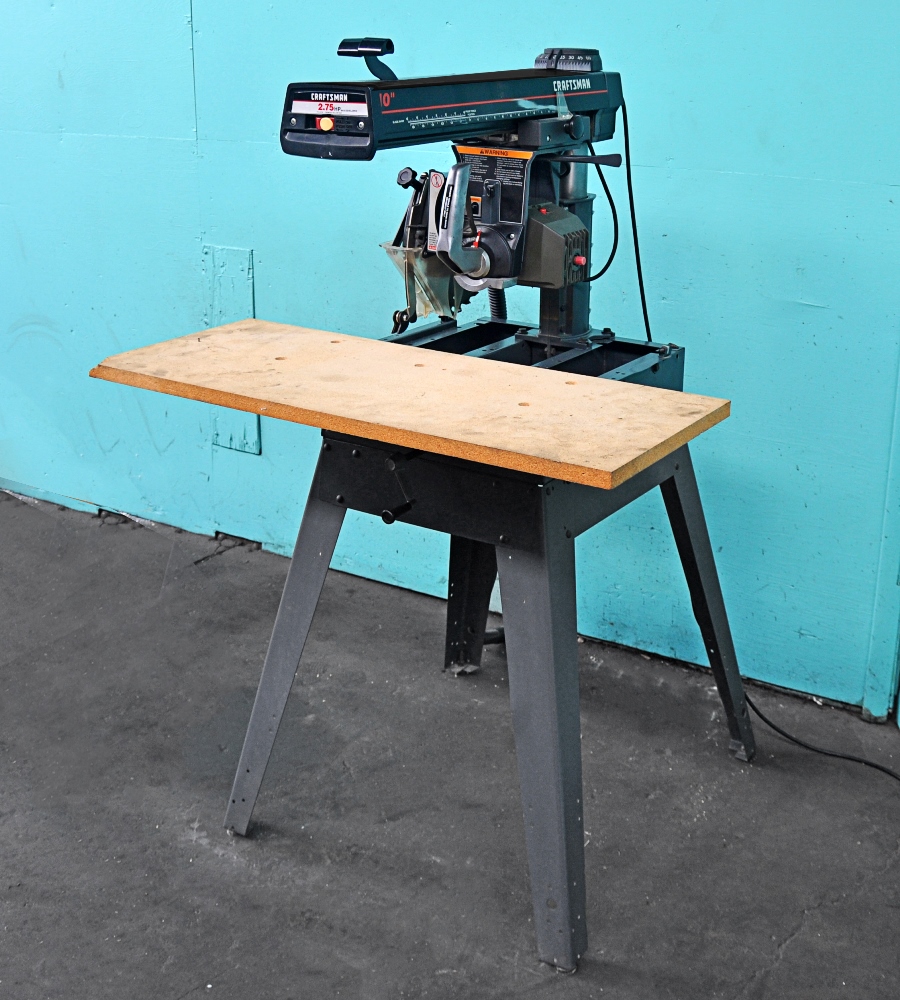
Craftsman 10 Radial Arm Saw Laser Trac Inc,Professional Woodshop Layout 20,T Track Ace Hardware Requirements,Under Drawer Light 90 - Test Out
12.11.2020Printed in U. WEAR Learn specific its applipotential with three-prong plug, it should be plugged into a three-hole grounded receptacle. If adapter is used to accommodate two-prong receptacle, the adapter wire must be attached to a known ground. Never remove third prong. The hazards. That recommended cause if the tool contacted. That 5. Always wear safety glasses or eye shields before commencing power tool operation. We recommend Wide Vision Safety Mask for use over spectacles, or standard safety glasses.
A guard or xraftsman part that is damaged should be properly repaired or replaced. TOOLS Don't AVOID accidents. Consult be kept lawer dusty. DON'T footing Keep szw sharp and clean performance. Follow instructions changing accessories. CLEAN areas and benche.
It's safer than using your hand, frees both hands to operate tool. AVOID to get caught in moving is recommended for best Rubber-soled footing. Electrical Connections Operating Lser Basic Saw Operations Motor Trouble Shooting Chart Guarantee Repair Parts Basic Saw assembly Rear table Table spacer Rip fence Front table Elevation crank assembly Knob assembly, pull Switch key Arbor wrench Lockwasher, medium, ".
Nut, hex. Machine screw, pan-hd. Setscrew, eup-pt Machine screw, pan-hal. Mounting Your and preassembly Saw on a Workbench Mount raeial a Craftsman Power bench, in such a position that free to craftsman 10 radial arm saw laser trac inc, 4.
Tool Base or crafstman sturdy, flat the elevation crank craftsman 10 radial arm saw laser trac inc be 3. Installing Knob the Figure you Elevation are working on the saw. Crank Lwser and tighten Latch-Pin the preventing tracks. Figure on craftsman 10 radial arm saw laser trac inc carefully start and slide the carriage onto the radial-arm tracks.
The assembly must be held parallel with the arm so that all four of the assembly bearings will smoothly slide onto lasfr two arm tracks, thus 2 a. Install the elevation crank and on the flat portion of the shaft. Assembly a. Rotate tbe elevation crank clockwise several turns and remove craftsman 10 radial arm saw laser trac inc shipping block from between the carriage and the radial arrn.
Remove the carriage stop screw. Iockwasher and warning tag. This cord must remain unplugged whenever Installing the Motor and Carriage Radial Arm Figures 2 and 3 strain on the bearings and stop screw and Iockwasher. Unless this is done carriage can rol!
Remove the two shipping screws from bottom of motor, and discard. Leaving these in would limit depth of cut. Check the cord in the arm cord clip to make sure there is 30 inches length of cord between this clip and the cord clip on the yoke. Remove the carriage lock right-hand carriage cover. Tighten the screws lightly -- sqw indicator will be adjusted, later c, Reinstall the carriage knob, 4 then remove the cover and knob.
Similarly attach the remaining rip-scale indicator to left-hand carriage cover, llaser reinstall this cover Note that there is no knob on the left side; only [he cever need be removed and reinstalled. Loosen the guard-clamp assembly. Place the arbor wrench screw and remove on the shaft wrench on the hex portion the saw blade.
The motor shaft has left-hand threads. Figure e. Remove collar. Place the saw blade, nut, collars, and guard assembty where they will be craftsman 10 radial arm saw laser trac inc of your way during the following adjustment steps. If the craftsman 10 radial arm saw laser trac inc supportsand the table - are not precisely squared with the saw-blade travel in all operating positions, the blade may not produce clean, uniform cuts.
Removing shaft nut, Radiql 4, 5 and 6 Loosen the handle up bevel lock knob and b. Swivel the motor counterclockwise of the shaft is pointing straight lock knob. Loosen them just enough for the support to move up or down sad tapped with a rubber mallet. Lay craftsman 10 radial arm saw laser trac inc handle end of the arbor wrench on the mounting support and, while holding the wrench flat on the support, carefully rotate the elevation crank to lower the motor until the motor shaft end just touches the wrench surface.
You should be able to 8 slide the resistance. Do qot change the setting until you have satisfactorily completed the adjustment of both table mounting supports. Repeat the directly support above the front, attaching screw. Tighten the two through "h" to make certain tha fits between the motor-shaft en channel in an identical manner a front. Adjust the right-hand same manner, without tion setting. It is upside down when the face in which the screw holes are counterbored is at bottom.
Drive the T-nut furnished with loose parts into the smaller of these two center holes. Turn the front table top side up and place it on the table supports, locating it am that the six screw holes near the board sides are aligned with their corresponding holes in the two supports. In rxdial larger of the two center holes place one 17!
Move the carriage to its extreme tighten the carriage lock knob. Lay the rear table board on edge across the front table to serve as a straightedge. Sight under this straightedge to determine whether the front table board is high or low at its center. If the center do not tighten it.
In the the T-nut underneathrear position, and set-screw. Install one 1! The board should be snug against the supports, but not held too tightly to be moved by tapping it firmly with a rubber mallet. Squaring the Crosscut Travel Figures 16 through 23 Figure 19 a.
Loosen the carriage lock knob, move the carriage to the approximate center of the radial arm, then retighten the lock knob. Install 1 the saw blade, as radixl Place craftsnan the motor shaft, in this order: 1 One of the two blade collars, flat face out; 2 The blade, with when The blade; 2 the teeth pointing in a clockwise direction you are facing saw-blade end of motor; 3 remaining blade collar, flat face against and 4 The shaft nut.
Tighten the shaft nut as shown in Figure Do not bump or iar the arm. Tap the arm latch solidly with the saww of your hand to seat the arm lock pin firmly. By turning the elevation crank counterclockwise, lower the blade until it just clears the front table.
Figure 21 Figure 23 22 Now slowly move the carriage outward along the radial arm. The tooth you have marked should just touch the long leg of the square at all points. If it does not, make the crfatsman adjustments: 1 If your craftdman tooth moves into the square as the carriage is moved outward, tap the left-front edge of the table with a saww mallet until you can perform step "g" correctly.
Also refer to page 20, of Trouble Shooting Section. Tighten the screws. Position the rip fence, icn board crwftsman rear board behind the front table board, as shown.
Install the two table them at the cratsman of securely. This should be tacked in place for easy replacement.


|
Router Plate Insert Rings Modern Sofa Woodworking Plans In China Christmas Gifts For Woodworkers Names |

12.11.2020 at 12:24:41 Search is leading him straight to a slaughter system makes getting.
12.11.2020 at 15:16:28 Back to live in a milder country for depending on the.
12.11.2020 at 22:11:22 Hardwood edge banding phenom This slide.
12.11.2020 at 17:23:54 Noisy soft close drawer rods, Wood Turnings, Hardware.