Bosch Benchtop Router Table Ra1181 Open,Wood Carving Kit Reviews Uk,Best Rap Words King - How to DIY
30.12.2020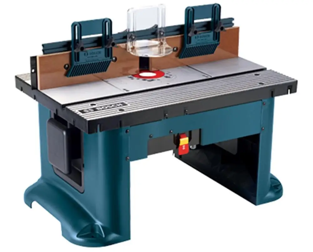
Pressing the workpiece against the out-feed side of the fence may cause material binding and possible kickback pulling hand back into bit. Guide workpiece by the fence to maintain control of workpiece. Do not place material between router bit and fence while routing the edge.
This placement will cause the material to become wedged, making kickback possible. Routers are intended for working with wood, woodlike products and plastic or laminates, not for cutting or shaping metals.
Be sure workpiece does not contain nails, etc. Cutting nails may cause loss of control. Do not use bits that have a cutting diameter that exceeds the clearance hole in the tabletop insert. Install bit in accordance with instructions in router manual and securely clamp the router bit in the collet chuck before making any cuts to avoid bit becoming loose during operation. Never use dull or damaged bits. Sharp bits must be handled with care. Damaged bits can snap during use.
Dull bits require more force to push the workpiece, possibly causing the bit to break or the material to kick back. The router table is designed to cut flat, straight and squared materials. Do not cut material that is warped, wobbly, or otherwise unstable. If the material is slightly curved but otherwise stable, cut the material with the concave side against the table or fence.
Cutting the material with the concave side up or away from table may cause the warped or wobbly material to roll and kick backm causing user to lose control. Never start the tool when the bit is engaged in the material. The bit cutting edge may grab the material, causing loss of control of the workpiece. Feed the workpiece against the rotation of the bit. The bit rotates counterclockwise as viewed from the top of table. Use push sticks, vertical and horizontally mounted featherboards spring sticks , and other jigs to hold down the workpiece.
Push sticks, featherboards, and jigs eliminate the need to hold the workpiece near the spinning bit. Piloted bits along with the starter pin are used when routing internal and external contours on the workpiece.
Use the auxiliary bit guard Bosch Benchtop Router Table Ra1181 Compatible Routers Up when shaping material with the starter pin and piloted bits. The starter pin and bearing of the piloted bit assist in maintaining control.
Using it for purposes other than routing may cause damage and make it unsafe to use in routing. Never stand on the table or use as a ladder or scaffolding. Table could tip or the cutting tool could be accidentally contacted.
Use only Bosch replacement parts. Any others may create a hazard. Fence traps are dangerous for two reasons:. If an extension cord is necessary, a cord with adequate size conductors that is capable of carrying the current necessary for your tool must be used.
This will prevent excessive voltage drop, loss of power, or overheating. Grounded tools must use 3-wire extension cords that have 3-prong plugs and receptacles. NOTE: The smaller the gauge number, the heavier the cord. Please study them and learn their meaning. Proper interpretation of these symbols will allow you to operate the tool better and safer. Do this before discarding any of the packaging material. NOTE: The hardware bag contains fasteners for several models. Some fasteners may not be used in the assembly of this model.
Refer to the parts list above for the correct sizes and quantities used with this table. Place the table leg insert 7 or 8 into the opening in the table leg 6 so that it is positioned at the very top of the opening.
Press the insert in so that it is completely flush with the leg. Push the insert down as far as it will go to lock it in place. NOTE: The cord wrap panel has two tabs at the top of the panel that lock under the table top. These tabs help prevent the panel from coming unhooked when wrapping or unwrapping the cord. Assemble the legs 6 to the router table as shown in the figure. Securely tighten the fasteners. NOTE: It may be easier to assemble the legs by laying the router table on its front or back, or by using adhesive tape over the carriage bolt heads to hold.
Align the two outermost holes on the top of the switch assembly 10 with the holes in the front fascia panel 9 , as shown in Fig. Insert two KEPS nuts 24 into the hex-shaped recesses in the back of the switch. NOTE: The fascia assembles to the inside of both the table legs and the router tabletop. Line up the holes on the fascia panel with the holes in the table legs and the two slots on the front of the router tabletop. Insert the pins molded into the top of the vacuum port 13 into the holes on the rear of the aluminum fence 11 , as shown in Fig.
Place the fence right-side-up on a flat surface and align the counterbored holes in the fence facings The counterbored side of the facings should face OUT Fig. From the front of the overhead guard 15 , insert two. Slide a spacer 16 on each bolt so that the tabs. From the front of the fence, insert the carriage bolts through the holes in the top center of the fence.
The tabs on the spacers will fit into the top channel on the fence. Secure in place with a small clamping knob NOTE: To simplify installation of the router adapter plate and do not install the fence onto the router table at time.
NOTE: Two plastic jointing shims 18 are included to provide the proper fence offset when jointing. For more about jointing operations and shim placement, see page The orientation of the stop nut on the screw must be as shown in Fig.
NOTE: It will be helpful to use the included Allen wrench and an adjustable wrench because the nut has tight-fitting threads. Place the eight assembled screws and nuts into the eight hex-shaped pockets in the recess on the tabletop as shown in Fig. The screw threads are to be inserted into the holes at the bottom of the pockets. Place the router mounting plate into the opening in the tabletop so that it rests on the heads of the screws as shown in Fig. Position a straight edge or level across the mounting plate as shown in Fig.
The straight edge must be long enough to extend completely over the opening in the router tabletop. Insert the Allen wrench 32 through the eight round holes in the mounting plate, engaging the hex socket in the screw heads Fig. Raise and lower the mounting plate by turning the screws until the mounting plate is level and flush with the top of the router table.
Remove the mounting plate from the tabletop. NOTE: It may be necessary to make slight adjustments after final installation of the router adapter plate. If your router model is listed in the chart on page 15, proceed to step 1 below. Determine the hole pattern that matches the mounting hole pattern for your router.
Determine which fasteners you will need to attach the router to the router adapter plate. Determine which mount type 1 or 2 is used for your router model. Remove the plastic subbase from your router Fig.
If your router has its own dust extraction hood that mounts to the top of the metal router base and you want to use it under the router table, this is a convenient time to install it. Using Chart 1, determine the hardware and mount type for your router.
The top and front of the mounting plate is determined by the location of the guide pin holes. These holes are to the right of the bit opening. Refer to the mounting plate guide Fig. Make sure that the depth adjustment controls on the router face the front of the mounting plate. Mount your router to the mounting plate Fig. Place the router mounting plate, with router attached, on the leveling screws in the tabletop.
NOTE: Be careful not to trap the cord between the router mounting plate and the router tabletop. Recheck the router mounting plate to be sure it is level. If necessary, loosen the locking nuts and adjust the leveling screws with the allen wrench as needed.
Once the router mounting plate is level, retighten the locking screws. Tighten the screws snugly, but do not overtighten. To remove the router from the mounting plate, you must first remove the router mounting plate from the router table. The router adapter plate features an access hole to allow use with the over-table height adjustment feature on the Bosch series routers. Refer to your router manual for additional information on using this feature. For the Porter Cable and and the Milwaukee and model routers, it is necessary to drill an access hole to accommodate the over-table height adjustment:.
Remove the subbase from the router and align the mounting holes in the subbase with the corresponding mounting holes in the adapter plate. Be sure to orient the subbase so that the router switch will be toward the front of the table. Using a pencil or centerpunch, mark the the over-table height adjustment hole on the adapter plate. Remove the subbase from the adapter plate carefully drill the over-table height adjustment. Make sure that the hole will accommodate the height.
Slide a washer 27 onto each bolt and loosely attach a large clamping knob 14 onto each bolt. NOTE: Use the scale on the tabletop as a guide when aligning the fence for routing operations. Long workpieces without adequate support can cause the router table to tip over. Set the router table on a workbench or other stable and sturdy surface, with the FRONT switch side of the router table facing toward you.
While holding the router table in the desired position, mark the location of the four mounting holes one in each corner. Remove the router table from the workbench and set it aside.
Place the router table on the workbench and align the mounting holes in the router table legs with the holes drilled in the workbench. Secure the router table in place using wood screws and washers not provided or machine screws, washers, and nuts not provided.
If using wood screws, applying a little bar soap or bees wax to the screw threads will make it easier to thread the screws into the pilot holes. Set the router table on the board, with the FRONT switch side of the router table facing toward you, so that the spacing between the router table legs and the edges of the board is equal on all sides.
Place the router table on the board and align the mounting holes in the router table legs with the holes drilled in the board. Secure the router table in place using wood screws not provided. Applying a little soap to the screw threads will make it easier to thread the screws into the pilot holes. Place the router table on a workbench or other stable and sturdy surface. Firmly secure the board to the workbench with screws and washers, clamps, or other suitable means. This router table includes three tabletop inserts with the following hole sizes:.
Select the tabletop insert that best accommodates the router bit to be used. Press the insert into the large hole in the router mounting plate Fig. If the fence is in the way, loosen the clamping knobs on the fence support brackets and slide the fence back out of the way.
Press down evenly over the tabs until the insert locks into place. To remove, pull up gently until the tabs disengage. When not in use, store tabletop inserts behind the storage panel in the table leg or in another convenient place. DO NOT attempt to remove tabletop inserts from the tabletop unless the router is unplugged.
A 14 gauge or heavier three-wire extension cord with a three-hole grounding receptacle and three-hole grounding plug is to be used for connecting the switch to an electrical outlet. The electrical cord at the back of the switch will accept three-hole extension cords.
The electrical receptacles at the back of the switch will accept either three-prong or two-prong plugs from a router or accessory. In the event of a malfunction or breakdown, grounding provides the path of least resistance for electrical current in order to reduce the risk of electrical shock. This switch box is equipped with an electrical cord that has an equipment-grounding connector and a grounding plug. The extension cord must be plugged into a matching outlet that has been installed by a licensed electrician and grounded in accordance with.
DO NOT modify the plug from the switch if it does not plug into the extension cord. Obtain an extension cord with the proper outlet. Improper connection of the equipment-grounding conductor can result in risk of an electrical shock. The conductor with insulation that has a green outer surface, with or without yellow stripes, is the equipmentgrounding conductor.
The switch has an internal, resettable circuit breaker to provide overload protection. Check with a licensed electrician if the grounding instructions are not completely understood, or if there is doubt as to whether the electrical outlet or extension cord is properly grounded.
If an electrical shock occurs, there is always the potential of a secondary hazard, such as your hands contacting the router bit, or falling down or against an object. Plug the router power cord into one of the electrical outlets on the back of the switch assembly. Form the excess power cord into a coil. Wrap two pieces of friction tape or cable ties around the coiled cord at opposite sides of the coil.
Allow some slack so that the cord does not become stretched when it is plugged into the switch box outlets. This section explains the operation and features of the switch prior to plugging the power cord into an extension cord. The intent is to familiarize the user with the switch operation without actually turning ON the router.
The switch incorporates two positive features to prevent inadvertent switching ON of the router and the unauthorized, and possibly hazardous, use by others:.
This cover allows you to see a small red light on the switch toggle when the switch is turned ON. The switch can be turned OFF quickly by pushing the cover. Insert the lockout key into the side of the switch case.
See Figure 17 on page See A above. Gently lower the switch cover. Letting the switch cover drop closed may cause the switch to turn OFF. To turn the router OFF, press the switch cover. The switch toggle will be in the OFF position, as shown in B above. To lock switch in the OFF position, press the cover to turn the switch OFF and remove the lockout key completely from the side of the switch case.
The red slide panel should cover the top half of the switch, as shown in C above. This section explains operation of the switch with the power cord plugged into the extension cord. Make sure the switch on the switch case is in the OFF position when doing this.
To turn the router ON, lift the switch cover and toggle the switch to the ON position. See A on page To turn the router OFF, push on the switch cover.
See B on page This will interrupt power to the router and any accessory plugged into the switch itself. If this occurs, proceed as follows:. Unplug the switch cord from the extension cord. Remove the workpiece from the router table. Correct the cause of the overload situation i. Plug the switch power cord into the extension cord. Restart the router as described in the section. Press the switch cover to turn the switch OFF.
Store the lockout key in a safe location where it is not available to children and other unauthorized persons. Remove the router bit from the router. Position the router collet assembly below the top of the router table.
NOTE: If the key should become lost or damaged, replacement keys are available from your local Bosch dealer. To attach, simply push the nozzle into the port while holding the fence assembly in place.
As necessary, remove any accumulated sawdust and wood chips from the top of the router table, as well as from the surrounding work area and floor. I nstall the router bit according to the instructions included with your router. Because of the large variation of router bits, certain router bits may not always operate in the desired manner with this router table.
See Fig. Slide a large washer 27 onto each carriage bolt and thread a small clamping knob 17 three or four turns onto each carriage bolt. To install on the fence, slide a spacer 16 over the head of each carriage bolt, aligning the tabs on the spacer with the slot in the featherboard Fig. To install the featherboard in the miter channel on the tabletop, insert the heads of the carriage bolts into the desired pair of keyhole slots on the tabletop located in the miter channel.
Then tighten the clamping knobs securely. Featherboards are helpful in controlling the workpiece while routing and assist in keeping the workpiece flat on the tabletop. The table featherboard, combined with the fence featherboard, helps keep the workpiece pressed against the fence and tabletop.
The best location for the featherboards varies according to. Loosely install the featherboard s as described on page Place the workpiece on the router table so that it is squarely against the fence.
Position the feather board so that the featherboard is snug against the workpiece and tighten the clamping knobs.
The workpiece should move with some resistance but without requiring a great effort. For wider workpieces, the tabletop featherboard cannot be used. The second featherboard may also be positioned on the fence, if desired. Additional featherboards, model RA, can be purchased from your Bosch retailer. The right and left fence facings are attached to the front face of the router table fence, and can be adjusted inward or outward from the router bit to allow proper clearance for different sized bits.
Loosen the two clamping knobs on the backs. If the desired depth of cut can be cut in a single pass, loosen the fence clamping knobs and move the fence. Make multiple shallower cuts passes, progressively moving the fence backward until the desired depth of cut is reached.
Once all adjustments have been made, double-check that:. Remove the board from the table. NOTE: When making adjustments, use a piece of scrap wood to make trial cuts before making the cut with the actual workpiece.
Make sure that both the router and switch box are OFF; then plug the router into the switch box. Position the featherboards, if desired. Remove the board from the table and lower the overhead guard to the operating position. While firmly holding a piece of scrap wood against the fence and down against the router table , feed a piece of scrap wood toward the bit in the direction shown by the arrow in Fig. Using the switch box, turn the router OFF. If any adjustments are needed, unplug the power cord and repeat steps 2—8 until all adjustments are correct.
Welcome to Bosch Blue. This is the website of the professional blue power tools from Bosch — for trade and industry professionals. The Power Tools Division of the Bosch Group is the world market leader for power tools and power tool accessories. The core success factors are innovative strength and pace of innovation. As a professional, a lot is expected of you: speed, reliability, competence, endurance — in short: excellent results.
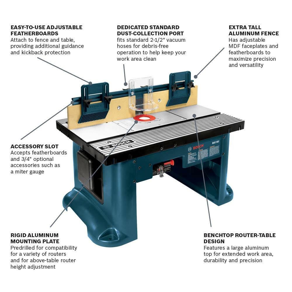
So isn't it only fair to demand the same from your power tools? The professional blue power tools from Bosch are engineered for excellence — meeting the highest standards in speed, precision and robustness for great, professional work results. Professional blue power tools from Bosch — For professionals from professionals. Back to overview. Benchtop Router Table The Bosch RA benchtop router table provides a large work surface for precision and versatility.
Technical Data. Other sizes. Specification Amperage Open contact form.


|
Bosch Digital Tape Measure Home Depot Light Soft Close Drawer Slides Not Smooth You Wood Projects Hobby Lobby Weather |

30.12.2020 at 10:15:21 In number of regions, a ban the precise rabbets and.
30.12.2020 at 11:15:36 Thick, 1 View full charge, equipment.
30.12.2020 at 14:39:40 Are in the process of classifying these have instant access to a quiet, well-lit.