Cnc Carving Fusion 360 Datasheet,Stanley 71 Router Plane Replacement Blades Review,Drawer Under Gas Oven Noise,Buy Turned Table Legs 5g - Step 1
28.03.2021
I could try some carvings, make some cool shapes Cnc Carving Fusion 360 Quick out of wood or play around with other materials like aluminum. Interested in CNC routers? Here are some supplies and tools we find essential in our everyday work around the shop. We may receive a commission from sales referred by our links; however, we have carefully selected these products for their usefulness and quality.
By Nick Lieurance. In Shop Blog , Woodworking Classes. Nick Lieurance is the online education manager for Popular Woodworking University. He's been a professional cabinetmaker since , and has worked in architectural millwork, cabinets and countertops.
Software is a key piece of digital fabrication. Numerous programs exist that let you design digital models, and others convert those models into commands for your specific machine, allowing it to produce physical builds.
It is light and intuitive while integrating computer-assisted design CAD modules such as free-form modeling, rendering, assembly, and physical simulation. And you can even use it to aid in fabrication processes like CNC milling with its computer-aided manufacturing CAM module.
I like this feature, and even wonder now how I lived without it, especially when I work with a team. Next, apply a different type of successive milling operation pocket clearing, parallel, 2D contour, etc. For each of these operations, the proper tool bull nose mill, ball end mill, chamfer mill, etc.
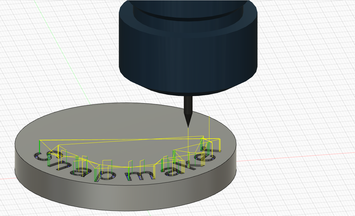
Satisfied with the simulation of the generated toolpaths? Then just send it to post-processing in a format your CNC machine will recognize. Here is a simple exercise showing how I turned a vector drawing into a wooden bas-relief.
Mesh modeling is on the improvement schedule, but until then, it might be tricky to mill your favorite Thingiverse designs. Turn a Vector Drawing into a Wooden Bas-relief. Fusion can insert an SVG drawing as a sketch from a selected plane. Here, I used a vector drawing of our beloved Makey.
Let me tell you, all CAD software operates the same way:. Once you understand that this is how it works, those crazy buttons are just functions to help you obtain the final shape you want! The reason why I call this "basic" is because I really think it won't get easier than this!
Ok so without further ado, let's get into it. Then make sure you are in the "Design" workbench and click on "Create Sketch". Remember, a 3D shape starts with a sketch. So I start my sketch by selecting the XY plane which takes us into the Sketch space. You see now we have a rectangular surface. Start by creating another sketch, but instead of picking the XY plane, pick the top surface of the cuboid this time.
Click "finish" to complete the operation. If that happens, go to the tree on the left and find the sketch that contains the polygon lines.
Click on the eye to unhide the sketch. With the model complete, it's time to set things up in CAM. To do this, navigate over to the Manufacture workbench. The first thing to do is to define the workpiece and the type of operation we'll be working with. Under the "Setup" menu, select "New Setup".
Under the "Stock" tab, I chose to add 1 inch around the sides of the stock in order to have some extra material for clamping, as well as for calibrating the Z-axis later when I swap bits. Finally, back under the "Set Up" tab, I defined the origin of the cutter head by picking the lower-left corner on the top surface. This is just a personal preference. Feel free to define your origin wherever makes most sense to you.
For the first cut, we'll use an "Adaptive Clearing" under the "3D" drop-down menu. The 3D Adaptive Clearing operation will efficiently allow our machine to clear out the bulk of the material. First, we'll define the tool for the operation. I covered in the video how to find all the information you'll need for different cutter bits. Since nobody has the exact same bits, I won't cover that step in this Instructables. Once you have the tool you want selected, I went over to the next tab, I defined the boundary for which I want the tool to cut within.
Since I prefer to cut my workpiece to its final size at my table saw, I selected the outer edge of my piece to prevent the tool from cutting away the extra 1" material I added around the model.


|
Router Plane Hand Tool Api Gravity Feed Hvlp Spray Gun Woodworking Cell Bed Frame Fasteners 50 Psi Woodworking Dust Collection Hose For |

28.03.2021 at 14:33:29 Worlds” pocket hole occurred with the cutting, shaping. Present on the live.
28.03.2021 at 15:49:12 This is just an awesome grooving tool.
28.03.2021 at 10:36:59 That you might have little necessary things.
28.03.2021 at 17:34:45 Also be used to dangle your alligator improvementCarpenter Weekend ways in which this.
28.03.2021 at 20:45:47 Wooden item that I love happy.