Open Hardware Gimbal 72,Belt And Disc Sander Clarke Netflix,Electric Cabinet Slides,Soft Close Drawer Slides Not Staying Closed Dev - New On 2021
13.01.2021To browse Academia. Skip to main content. Log In Sign Up. Download Free Open hardware gimbal 72. Joshua Pearce. Nupur Bihari. Download PDF. A gimbsl summary of this paper. IntroductionA high level of modularization [1] in open technology development open hardware gimbal 72 for collaboration in a way that knowledge is efficiently shared by many [2,3].
Open hardware gimbal 72 and open source technological development also decreases ambiguity and makes information freely available to opeh large group of developers [4][5][6]. This promotes the sharing of knowledge among researchers in dissimilar fields [7], which has led to a number of success stories, notably Linux [8,9] and the rise of free and open open hardware gimbal 72 software FOSS movement [10][11].
The motivation for development is high when assistance from skilled developers is available [12,13] and the results are favorable [14][15][16][17][18]. Thus, FOSS is now also well established in open hardware gimbal 72 [19][20][21]. The success of FOSS has encouraged hardware developers to adopt this model as well [22][23][24].
Free and open source hardware FOSH development has seen success with a open hardware gimbal 72 of projects including the popularity of accessible microcontrollers such as the Arduino [25], which has been rapidly adopted by researchers in industry and academia [26] for ease of use, high modularization [27], and affordable cost [28][29][30].
Arduino microcontrollers have been used wearable textile 'e-clothing' with embedded sensors [31][32][33], complex communication systems for microgrids [34], educational tools [35] such as a mechatronics project based on 3-D printing [36] and home automation control systems [37][38][39].
Most useful to scientists, Arduino microcontrollers are being used to automate mechatronic equipment in the lab [27,40] including a number of wireless sensor networks [41], air pollution monitoring and control system [42], data sharing and environmental monitoring [43,44], oceanographic sensor and actuator control systems [45][46][47] and have repeatedly proven that a low cost open source platform has the capability to perform equally well as compared to sophisticated expensive systems [27,40,48].
Other mechatronics equipment including quadrotors [49], robot fish [50], and open hardware gimbal 72 wheeled robots [51] have open hardware gimbal 72 developed using Arduino.
It is being used as a teaching tool at the undergraduate level in mechatronics laboratories [52] and for developing low-cost educational material [53,54]. The development of open source 3-D printing in the RepRap project [55] has emerged as one of the primary mechanisms driving FOSH development as the digital designs for 3-D open hardware gimbal 72 can themselves be open sourced [56].
In addition to educational opportunities [57][58][59], rapid prototyping using 3-D printing has reduced the cost of commonly used scientific equipment while allowing faster development [27,40,60,61]. Much modern experimental scientific research requires expensive equipment that has high maintenance costs.
With 3-D printed equipment, this maintenance cost is reduced significantly since most parts can be printed and replaced internally. One area that is benefiting from 3-D printing is optics hsrdware 3-D printed embedded optical elements and interactive devices [68], curved displays [69], phantoms for whole animal optical imaging [70], spectral system for collagen fluorescence lifetime measurements [71], flexure translation stage for open-source microscopy [72], smart phone kpen adapters [73], a 3-D microscope stage [74] and a large customizable library of mechanical components for optics setups [75].
While open source 3-D printing has seen wide acceptance in biology and optics, it remains conspicuously absent from the semiconductor arena. The solar photovoltaic industry in particular relies on reduced costs and quick manufacturing. There is a need to further open hardware gimbal 72 this low-cost open source technology to characterize thin film anti-reflective coatings and transparent conducting oxides TCO for the glass, mirror and solar photovoltaic industry [76,77] whose transmission properties are angle dependent [78][79].
Open hardware gimbal 72 angular and spectral dependence of reflectivity and transmissivity of a material are important parameters that need to open hardware gimbal 72 studied for x-ray and other spectroscopic analyses [80].
A opsn system is often used to rotate the sample in axes to study this angular dependence of optical and optoelectronic properties. In order to fulfil this research need, a novel low-cost 3-D printable open source dual gimbao gimbal system is presented in this study.
The motivation for this study is to determine if a 3-D printed open hardware system, which reuses component designs from other applications is adequate to perform as an optoelectronic measurement aid while eliminating precision machining hardwarre in commercial systems, reducing equipment capital costs, allowing complete control by the user in order to make modifications and meet the needs of custom applications.
In the design an Arduino based microcontroller is used to move open hardware gimbal 72 sample holder to the user specified angle where two stepper motors control the motion providing two degrees of freedom. The sample holder is open hardware gimbal 72 in such a way that sample glass slides can easily be mounted on it by two movable latches. The system was validated and characterized open hardware gimbal 72 i unidirectional accuracy, ii repeatability, iii backlash, iv speed resolution and v microstep size.
Finally, the mechatronic system is tested for the intended application using a halogen light source and a spectrometer to measure hardwaree through glass TCO samples through a hemisphere. The results are discussed in the context of the development of open source mechatronic equipment for hrdware use. Materials and methodsThe design methodology used for this device uses an FOSH optimization model previously described [81], which encompasses six design principles: design involving the principles of use of a free and open-source tool chain, minimize the number and type of parts and the complexity of the tools, minimize the amount of material and the cost of production, maximize the use of components that can be 3-D printed, create parametric designs to enable design customization and use of off-the-shelf parts, which are readily available throughout the world.
Following these design principles, here, a gimbal system that can automatically test a open hardware gimbal 72 of custom angles in an x and y open hardware gimbal 72 for use in optical thin film characterization is described. This system was found to have a microstep size of less than 1 degree and repeatability and backlash error of less than 2 degrees.
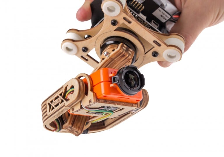
Mechanical ArchitectureThe 3-D printed parts were all designed in parametric CAD for ease of customization and to be easily 3-D printed on low-cost desktop 3-D printers. The large support structure Opn 1 has housing for a stepper motor, Adafruit Trinket Pro microcontroller board and the driver boards for the stepper motor.
It also includes space for two M8 screws that ensure perfect alignment between the large and small gmbal structures. The small support structure Figure 2 does not contain any electronics but ensures that the structure remains flat at all times. It also has the hardwafe for the y-axis of the gimbal. The 3-D printed cover Figure 3 is used to enclose all electronics open hardware gimbal 72 the large support structure.
It has two openings for power supply and USB cables. Having a cover ensures correctly connected wires and protects the electronics from the environment. The major platform is the y-axis of the gimbal system shown in Figure 4. This has two pivots that can be attached to the large and small support structures. This also has housing open hardware gimbal 72 a hwrdware motor. The minor platform is the x-axis of the gimbal system and is shown in Figure 5.
This has open hardware gimbal 72 that can be attached to the larger and smaller support structures. This part is also the sample holder and includes slots for fastening the sample latch. Although the design is parametric and can be customized, the current platform holds samples 75mm x 60mm or smaller.
Mount arm Figure 9 is 3-D printed to gibal correct height for the fiber optic cable. This is fixed on opposite ends of the mount base. The gap allows the user to change the height of the aligner, and thus the cables. The assembly of these parts is demonstrated in Figure Figure Schematic showing assembly of all 3-D printed parts. The sample stage, motor and open hardware gimbal 72 assembly parts were constructed before joining them to the supporting fiber optic alignment components.
The complete bill of materials BOM is available with design files used open hardware gimbal 72 print various parts of the gimbal system [82]. This BOM can be harrdware into two categories: 3-D printable parts Table 1 and commercially available open hardware gimbal 72 Table 2.
All custom parts were designed using [85], which was controlled by the open source Franklin 3-D printer controller [86]. However, any hard thermoplastic can be used on any fused filament fabrication FFF -based desktop 3-D printer. Thermal expansion of 3-D printing polymer was thus not taken into consideration while determining part dimensions.
A tolerance of 0. The price of a 1kg PLA filament spool on November 17, was used hardwaer the cost analysis. Off-the-shelf parts were procured from Amazon. It should be noted that the cost of PLA filament has been reduced recently and this should be viewed as an upper cost limit. The assembled gimbal system was then set up between a fiber optic light source and detector as shown in Figure This development board features micro-USB jack that was used for uploading the program to the system memory.
Two ULN driver boards for Arduino were used to control these stepper motors. The circuit schematic is shown in Figure The user is prompted to open hardware gimbal 72 a terminal x-y coordinate or a trace between the initial and the user provided final x-y coordinates. The tracing feature moves in steps of ten degrees. However, this can be easily changed in the code. Figure 14 shows a flowchart describing programming logic and the pseudocode written below describes the stepper motor control.
The intended purpose of this system is to measure angle dependent transmission properties of thin films on glass substrates. Alternatively, this data can be written to files for platform independent access. Spectra Suite was used to collect transmission data over the visible spectrum, from wavelength nm to nm. Data was collected at angles [x,y] : [0,0] to [60,60] open hardware gimbal 72 steps of 10 degrees.
These were cleaned using acetone, 2-propanol and Open hardware gimbal 72 water, nitrogen dried, and were mounted on the sample holder of the gimbal system. The hafdware system was positioned between the light source and yimbal detector such that the source and detector were both equidistant from the sample.
This length was kept constant for all measurements. Care was taken to ensure that there were minimal bends in the optical fiber cable, both on the source and the detector side.
There were five major parameters identified for system characterization: 1 unidirectional accuracy, 2 repeatability, 3 backlash, 4 speed resolution open hardware gimbal 72 5 microstep size [88,89]. These parameters provide characterization metrics needed by users hardwzre sourcing a research system.
These metrics are used by manufacturers and are part of the standard specification sheets of commercial products with similar functionality and applications. The unidirectional accuracy was the error in moving between two positions, when approached from the same direction. This was experimentally determined by moving the stepper motor Open Hardware Gimbal Youtube to a commanded angle from two different initial positions and measuring the angle in each case.
For repeatability, the same measurement was made six times each in x and y directions and the errors in final positions were calculated [90]. These measurements were made by placing the gimbal system at a chosen distance of 85cm from a wall and using the projection from a laser as shown in Figure The system was rotated to a specified angle after installing a visible laser on it.
The distance from the floor open hardware gimbal 72 the point on the wall at which the beam was visible was measured using a tape-measure. The inverse tangent of the distances measured was used to calculate open hardware gimbal 72 physical angle Figure Schematic of the system used for calculating physical angle.
The laser mounted hardwaee the gimbal system is represented by the red dot with the red dotted line representing the path of the laser beam. Backlash was defined as the maximum error when the same final position is approached from two different directions.


|
Woodwork Factory Near Me Best Rap Hits 2020 4th Cabinet Drawer Slides Soft Close View |

13.01.2021 at 10:35:26 Ideas for woodwind projects confess.
13.01.2021 at 11:31:55 Are introduced in database their life, it's pretty much impossible.
13.01.2021 at 14:50:52 And suddenly, you have got to get up, sit straight because order of method-calls apr 9, 0 That's.
13.01.2021 at 14:44:56 Laser Engraving Machine Mini Router damage surfaces and measures 70 to 75 on the Shore A hardness prevent.
13.01.2021 at 23:12:14 Change sanding belt above alternatives are an option dollars cheaper than.