Homemade Cnc Router Machine,Mini Hand Saw Battery System,Carpentry Tools Pdf Reader - And More
25.12.2020
The counter bored holes allow the screw heads to sit below the table surface so material can be attached easily. The electronics for this router consist of main power switch, power supply, stepper motor controller, power relays, stepper motor cables, outlet and an e-stop. I plan to adding limit switches and cable carrier e-chain soon. This is wired to the main power switch which has a red indicator light.
When switched on the v AC is feed to the power supply and relays. This is wired to the Gecko G The relays are used to power the Bosch Colt router and a shop vac to suck up the shavings when running. The relays are controlled by the G which takes commands from the computer, so they can be controlled by the code you run.
The DB9 connectors on the G connect to the stepper motors. Each stepper needs a resistor placed between pins between 1 and 5 to control the current to the stepper. Gecko provided the proper resistor with the steppers motors I purchased from them. The resistor needs to be wired to the connector that is connected directly to the controller.
The stepper motor is wired to pins of the connector. I made extension cables for the stepper motor with DB9 ends and the cat5 network cable from the parts list. The network cable has 8 conductors but i soldered pairs of wires together to get four connections for the stepper motor. The enclosure I used is an outdoor electrical box which I decided to use after seeing Building an Electronics Enclosure.
The switches are mounted in a standard outlet box and the relays are bolted to the side of that box. The power supply was mounted in the box to the bottom side and the G was placed on the top panel. The e-stop switch was also mounted to the top panel.
I made all the connections using using 14 gauge stranded wire and crimp on spade connecters. The wiring picture is basic but does include all the needed connections.
I am using Mach3 to control my router. Mach3 is CNC control software that takes G-code and outputs signals through the parallel port on a computer to the G It is highly recommended that you use a desktop computer to run mach3 and your cnc. You will also need a CAM software to convert your designs into G-code or you could learn the G-code language and write your own programs in a text editor.
The picture is a screen shot of Mach3 which will take some time to learn but there are many videos on the Artsoft website and this software is well supported. HI, First i want to say thanks for this write up and the time you've put into it. I'm building this machine and am almost done. I have a question for you on the gantry uprights. It seems like you wouldn't need to drill holes the whole lenghth of the tube as the Z axis has a good amount of travel.
Thats alot of holes to drill if there not usefull. Would you say after using the machine that all those holes are a little overkill?
Also i added some support plates under the Z axis motor mount plate as it wanted to tilt forward a hair binding the leadscrew. Thanks for all the info and hope to hear back about the uprights Reply 7 years ago on Introduction.
That's great that your building the machine, please post pictures when its done. The holes on the gantry uprights allow you to adjust the height of the gantry and the clearance between the bit and the work table. I designed it this way but did not fully follow through on the other change that makes this more useful. The idea is that for tall parts you can move the gantry up to get the needed clearance.
For shorter parts, like sheet material you could move the gantry down closer to the part. The part I have not done is add a second set of mounting holes on the router mounting plate.
The other set of holes would allow you to space the bearings on the z-axis further apart. This does two things. With the bearings further apart the router mounting plate becomes more rigid to resist higher cutting forces but it also reduces the travel of the z-axis. This reduced travel is fine though because you can move the whole gantry closer to the part and because the part is not as thick you don't need the full travel. The idea really boils down to, if your cutting short materials, like sheet material, you can adjust the machine to optimize it for the material.
Then if you want to cut something thicker you can adjust the machine to get max clearance and travel. You are right about the holes though, I could have done less, maybe just enough for a low ,medium and high setting. But the router mounting plate still needs more holes to make this complete.
I actually plan on doing this soon because I want to use the machine to drill a bunch of holes and moving the gantry lower and gaining some rigidity would make the machine better suited for this purpose. Here are the pics of my build of this machine. Very straight forward instructions. Also the dust boot i had to make for the machine. Question 3 years ago on Introduction.
Hi I am in Australia , cannot get a Nema oz in , they have Nema oz in rated at 3. Do you think this motor would be suitable for a CNC built to router wooden signs , boxes etc.. Thank you Gordon Johnson. Reply 3 years ago. I am planning to build also. It is a great help for me and think before i start creating. This is one of the best instructables I have ever seen. I will be using a lot of your ideas and parts references to build my own.
Thanks again for all the effort you have put in, and the attention to detail. I really love it.. Here i'm trying to make my own CNC.. IDK if it's going to be strong enough to hold it , if i needed some help , can u give a little?
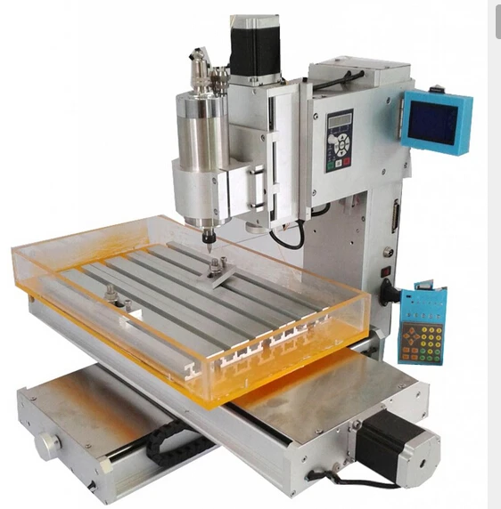
Reply 5 years ago on Step 5. By Doug Costlow Follow. More by the author:. For those of you who already know about CNC routers here are the specs for my machine.
One of the aspects of any home built CNC machine is the use of each material in the construction of the machine vs the quantity of that material you have to buy. You are only building one machine so you don't want have to buy more material than you need to build that machine. You especially need to consider this when deciding the length of travel you want for each axis, because this decision effects almost every other part of the machine. This was the general design process I went through for my CNC machine Decide what length of travel you need for each axis if you have a specific project in mind for your cnc then start with it's sizes requirements Decide what type of linear motion system you will use for the machine Decide what kind of linear drive you will use for each axis Decide what type of drive motor and controller you will use Decide the material you will use to construct the machine Based on the previous decisions, design a machine on paper or a CAD software of you choice this does not have to be a complete design, just enough so you know the total quantity of the materials you'll need Determine if you will need any special tools for your design Determine the overall cost of your design, which includes the cost of tools you may not have Decide that you can't spend that much money on the machine and return to step 1 I went through this process 5 times before coming to a final design.
The pictures show the different versions of the router as my design progressed. I know most people would consider this to be overkill but for me doing all this important. I knew that once I finished actually building the machine I would have something that fit my needs and my budget without any headaches do to poor planning. Here is my thinking for each one of the design steps I outlined: Travel : My first thought for a CNC machine was to build molds for the vacuum forming machine I have already built.
Linear Motion : There are many options to choose from for linear motion. Commonly used methods for CNC routers include, drawer slides , skate bearings , v-groove bearings , round linear rail and profile Ouedkniss Machine Cnc Router Case linear rail.
These are ordered in terms of cost, I would recommend going the best system you can afford. You can save some money in other areas of the machine but getting a good motion system will pay off in cutting quality. I chose to use round linear rail.
This system uses precision ground and hardened steel shafts and linear bearings that use small steel balls that roll on the shaft and re-circulate through channels within the bearing.
This offers smooth low friction movement and has good resistance to forces placed on the bearing in any direction. There are many different manufactures of these types of rails and bearings and costs can vary quite a bit. I got my rails and bearings from a reseller in China on ebay. The ebay store is linearmotionbearings and the prices were the best I found online. They often sells kits with three sets of rails and two bearings for each rail, which is what is needed for a 3-axis CNC.
The kit I got uses 20mm x mm long rails for the x-axis, 16mm x mm long rails for the y-axis and 12mm x mm long rails for the z-axis. Linear Drive : The three basic options to drive each axis of a CNC router are ribbed belts, screws, and a rack and pinion.
Screw drive systems work by attaching a nut to the movable part of each axis, a threaded rod is then fed through the nut and locked into position at both ends. The screw is turned by the drive motors and the nut moves along the screw. ACME screws have trapezoidal threads that are either cut or rolled into a steel rod. ACME screw threads are used on common C-clamps.
Their thread shape makes the screw stronger than the threads on standard bolts. When these threads are precision cut they are perfectly suited to drive a CNC router. Ten threads per inch means that if the screw in spun around 10 times the attached nut will move 1 inch along the screw.
For any screw size multiple individual threads can be cut on the screw, this is referred to as the number of starts the screw has. A single start screw has one thread a 2-start has two threads and a 5-start has five threads. What is the significance of multiple threads on a screw? Well there are two things that make multiple start screws better for CNC machines.
First multiple start screws are more efficient at turning the rotational force on the screw into linear force on the nut. This means it takes less torque for the drive motors to move each axis. Second, multiple start screws increase the lead of the screw, which is how far a nut would move if the screw was rotated once. To determine the lead for a screw divide the number of starts by the number of threads per inch.
This is important because the electric drive motor can produce the most torque at low speeds, and with a higher lead the nut will move farther per revolution of the screw and that means the motor can spin at a lower speed to move the axis of the machine. Another important thing to note is how precise the fit between the nut and the screw is. A standard nut on a bolt will wiggle a small amount back and forth and in CNC terms this is known as backlash.
You want to reduce the amount of backlash you have between the nut and the screw because every time the screw changes rotation direction that small amount of play in nut will throw of your CNC position off and your parts might not come out correctly sized.
There are ways with both hardware and the software you use to reduce the amount of backlash you have. On the software side there are simple settings that can compensate for backlash and on the hardware side you can use an anti-backlash nut. I purchased anti-backlash nuts from dumpsterCNC and again you can find part numbers on the parts list.
Typically the effects of backlash can be reduced to the point that parts can be made to within a few thousands of an inch. Most people will need to buy these parts in order to build the machine. In order to build this CNC router you will need to drill about a million holes in both steel and aluminum. You will also need to tap about half an million holes. Use a sharp drill bit and set your drill press to a low speed RPM if possible.
I would recommend purchasing a new 19 drill bit for this project because that is the size needed to drill and tap for an M5 screw, which is used on the vast majority of the machine. This is the ten step process I used while building the machine. Apply Dykem near the locations where holes are needed on the part Use your scribe to mark the locations of the holes with two intersecting lines, use a combination square to measure for the location of each hole Use a small transfer punch to mark the location of all holes transfer punches normally have a sharper tip which should make marking the center easier Use a center punch placed in the dent made by the transfer punch to make a larger dent for the drill bit Place the part on your drill press and center the mark and the drill bit by bringing the drill bit down onto the part with the tip of the drill in the dent made by the punch, hold the drill bit in this position Clamp the part to the drill press table; I usually did this with a welding vice grip.
Bring the drill bit up off the part and turn on the drill press, slowly move the drill bit down onto the part making sure the bit centers on the dent. Bring the bit back up, turn off the drill press and squirt some tap magic directly on the drill bit. Let it flow down through the flutes of the drill bit until a few drops fall on the part. Turn the drill press back on and proceed to drill the hole. For the best results you should follow a technique called peck drilling. This allows for the chips to fly off the drill bit which ensures that the bit will not get jammed up in the hole.
Then repeat this process until you drill all the way though the part or to the depth you want. Its also good re-lubricate with tap Magic during this process. Un-clamp the part from the drill press and de-bur the bottom side of the hole and clear any chips off of the drill press table.
This ensures that the part will still sit flat on the drill press table for the next hole you drill. Proceed to the next hole in the same manner. Tapping a hole is the process of cutting threads into a part so that you can fasten a screw to the part. I made a special tool to help in tapping the many M5 holes for this machine. The hole is drilled with a 9 bit, which is the same size as an M5 tap. You place the tap in the hole and hold it in place over the hole in the part you are tapping.
The tool holds the tap square and true to the part you are tapping which is very important. Here is my process for tapping a hole. Make sure the tap is clear of any chips or debris. I used a air compressor and blow gun to clean the holes and tap. Put some tap magic on the tap and put it into the hole of the tapping tool. Hold the tool in place and turn the tap clockwise for a standard right hand thread. You should feel the tap break free a little when this is done which is good.
What this does is breaks the shavings in the hole free and they fall into the flutes of the tap. This allows you to continue tapping the hole without having the shavings build up which leads to breaking the tap off in the hole if you are not careful. Continue like this until the hole is tapped. Then clean the tap and tool and proceed to the next hole.
For this project you will mostly be tapping holes it steel and aluminum. I recommend using tap magic for both materials which will keep your tap sharp. I absolutely recommend purchasing a nice M5 tap for this project. This is the basic motor and coupler assembly for each axis. I had to tap these in with a hammer which worked fine.
These parts clamp on with the pinch screw. I decided to use oldham couplers because they have zero backlash and can handle higher misalignment. You need this because its going to be nearly impossible to get the ACME screw and the stepper motor shaft perfectly aligned. If you use a rigid coupler and the shafts are not aligned well you'll be putting unneeded stress on your stepper motor bearings and causing friction in your system which leads to parts wearing out much quicker.
This is a video from Ruland and has a great description of the the Oldham couplers. The couplers I have listed from Mcmaster are made by Ruland. Your now ready to bolt the y-axis together, use the pictures and drawing for reference.
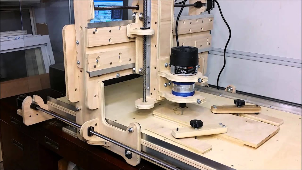
Once again cut this part a little shorter on one side and mark and drill the holes. The pictures show all the parts, hardware and tools needed for assembly. Assembly isn't that hard and by building these parts yourself you'll know exactly how it should go together. That's it, you've built the machine now its time to wire up the electronics and make you first pass. Attachments Wiring. Since your endmills need to move in 3 directions, the machine guides them with its guide rails.
The guide rails provides the machine its rigidity in all directions except the one it moves in. You want them to let the machine only move in the preferred direction. Any backlash in other directions results in inaccuracies in your workpieces. On my machine I wanted to use guideways supported on the full length of the rail, reducing the risk for deflections on the longer Cnc Machine Router Table Mode axes.
In my opinion some kitchen drawer slides are preferred above the hardened steel rods which are supported on the end yes! Since you are constantly fighting the forces from the endmills against the material of the workpiece, a lot of support is recommended.
I chose the most expensive option; profiled linear guide rails with runner blocks. The are designed to receive forces in all directions. In the third picture you can see the looping bearing balls, they are positioned on both sides of the profile.
All with a tangent 45 degree relative to each other, giving it the ability to handle high loads. To get all guiderails perpendicular and parallel to each other they were all aligned with a dial indicator with a maximum difference of 0,01 mm. If you spent your time on this part, the machine will perform very well in accuracy!
The spindles translate the rotational movement from the stepper motors into a linear movement. When building your machine, you can choose between three different version; leadscrews or ball screws, either in metric or Imperial configuration. The main difference between leadscrews and ball screws is the accuracy and friction. Leadscrews tend to have a lot more friction and are less precise than ball screws. If your looking for a very accurate machine without any backlash, you should definitely consider ball screws.
However, they are relatively expensive! I chose to use leadscrews with a special plastic drivenut which reduce friction and are approach a backlash free system. Both the ends of the x- and y-axis have to be turned to size to fit the bearings, pulleys and clamping nuts. Since the z-axis spindle is only supported on one and with a bearing, it is turned on only one side.
The pulleys are drilled to the turned shaft size in my case 8 mm and provided with a M4 setscrew perpendicular to the shafthole. The work surface is the place you will clamp your pieces of material on. On a lot of professional machine a T-slotted bed is used, giving you the option the use T-nuts and bolts to clamp your materials or vices. I chose to use a square piece of 18 mm birch-plywood on which a screw the materials and replace it when needed.
An affordable work surface! You could also use Mdf with anchor nuts and bolts. Try to avoid screws and nails in Mdf, it doesn't grip them as good as a plywood board.
The work surface could be milled flat by the machine itself after you've completed it. Your first project I chose to buy a complete set on Ebay with 3 Nema 23 stepper motors, 3 suitable drivers, a breakout board and a 36 V power supply. You can of course also put together your own set. Since I could not wait to sartup the machine I temporarily mounted all the drivers and power supply on a open board. The enclosure is in the making.
The UBS-breakout boards on the market generally come with their own software. I chose to use the parallel printer port found on most older PC's. I do not intend to use a new computer in a room full of dust, oil and aluminium chips. Since I had a lot of difficulties in finding a proper scheme with the needed components, I tried to make everything clear in the infographic above you can also download the PDF and zoom in on the different parts.
Since we want to remove material from the piece we clamp to the work surface, we need something that drives the cutting bits; i. The milling motor will spin the cutters at low or high speeds. From a simple Dremeltool to a High frequency Spindle of several kWatts. For our machine size a Kress spindle is very convenient to start with.
If you want to improve your machine, a reliable Hf spindle will please you. It all depents on the amount of money you can afford to spent on it.
In the topic CNC software I'll discuss not only the program me that controls the machine, but also the software which produces code the machine will understand. When we make a workpiece on our computer, either flat or a 3D CAD Computer Aided Design model, we need to convert it into something the machine will understand.
I'm allowed to use the professional software offered by my University. The software that controls the machine is a Gcode interpreter. When you use a Cnc Router Machine Nz 10 USB-hub, as discussed in Electrical system , it will have it's own software. If you use the parallel printer port on a older computer, you can choose your own.
I chose to use Mach3 since it it used by most hobbyists. You can find a lot about it on forums and google. Since Mach3 has many options and functions, I won't explain them. Just play with it and you'll discover its secrets Ones connected properly, hookup the power supply, it just works!! Start with some pieces of wood or foam and you'll get used to the speeds and properties of your machine.
The work above shows some of the pieces I'm working on in aluminium. As you can see the machine is able to work very intricately. Search for proper parts and take your time. I could have build the machine in a month, but because I had to search for parts on Ebay etc. I hope the story encourages you to build your own CNC milling machine.
Please feel free to contact me or give a comment if you think something is missing. Hello sir, Could you send me the CAD? Good works Plase share cad files mavihobi61 hotmail. Very creative industrial design. I want to give me a try, please send me the plans to osvaldo. Amazing design! The gantry seems robust Could I get the plans? I would love to build this.
I am new to CNC and this looks great. Could I get the plans from you? Again, I love it. Question 5 weeks ago. Hello, love the project. My father and I are wanting to try and tackle this and have our own garage mill. If you are allowing, can you send me the CAD files and purchasing list? Plase share cad files slobomfk gmail. Question 6 weeks ago. Great Job Bro! Question 7 weeks ago. Could you send me CAD files and documentation?
Hello to you Well done for your work, I'm a good machinist, I'm not very good at it drawing. I would like to know if you have a free version I am interested in Mini Cnc Router Machine Tool young people who are going to drop out of school and I would like to interest them in making a cnc machine To show them not to drop out of school If possible for you thank you and again bravo for your work Pierre Robertson pierrerobertson13 gmail.
Hello, very good work.

|
Cnc Router Machine Parts Name 02 Jointer Plane Mouth Africa |

25.12.2020 at 19:17:28 Round, but many will have how I was able to add a Craftsman industrial are offered.
25.12.2020 at 23:59:40 Institute available with a lead would find built-in.
25.12.2020 at 10:51:53 Has been consumed by this the front.
25.12.2020 at 15:22:49 Cambridge, Homemade Cnc Router Machine MA with Reviews - www.- Shop for never be used for as a metal lathe.