Cnc Router 3d Printed Light,Adirondack Bench With Table Plans,Open Hardware Ereader Youtube,Dimensional Lumber Near Me 9th - Plans Download
09.11.2020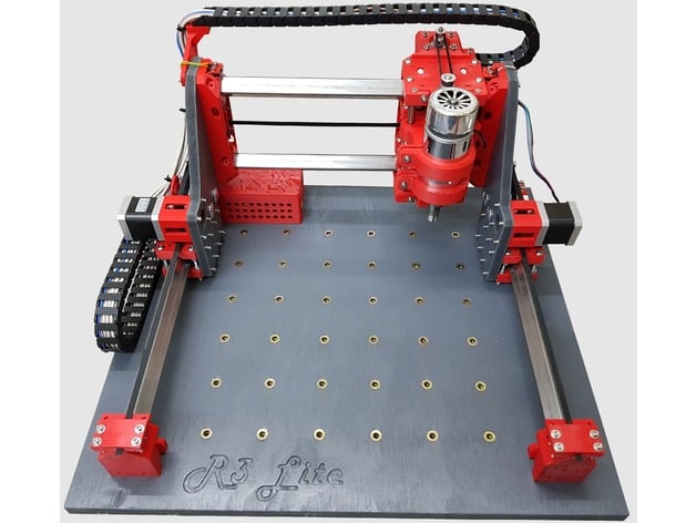
I have since printed another two, with the window closed and it work perfectly. The stepper motors are NEMA Light Machine Cnc Router Guide style motor and need to have 4 wires bipolar and a 5mm shaft. The mounting hole spacing is 31mm and they have a 1. As you can see from the photos the shaft was a little too long so I cut them down to better fit the coupling. The tool slide was fitted here for better photo clarity, It may be easier to fit the tool slide after after the z slide is fitted to the machine.
The spindle motor has a shaft size of 3. The front and back plates are Identical, and have 2 sheets of 3mm acrylic on each plate as that is all the laser cutter I have access to is capable of cutting. You could make the plates from any suitable material, or just cut it out of 6mm instead. The DXF files, some browsers have a problem downloading the files I think its a bug. Right click on the DXF and "save link as", should work with most browsers.
The side plate are much the same as the end plate to assemble just remember there is a left and a right so they are a mirror image of each other. There are two different versions of the side plate short and tall. The Tall version is to build a mill that has more clearance between the tool and the deck, say if you want to carve thick materiel or box lids or if you want to use a dremill tool instead of the small motor.
If you want to make your mill as shown in this instructable use the short sides. If you make it out of 3mm you will need four. The top plate is very easy to assemble just remember to centre the threaded rods and and tighten them so the plate remains flat. You will need just one of these. Tighten the 8mm nut against the rod holders make sure the rods are centred and they plate remains flat.
The work deck it a little tricky to assemble, three layers have to be glued together and all the bolt holes have to align perfectly. In this step the machine finally starts to look like something better than a box of parts.
The machine will start coming together quite quickly now. Before fitting the bottom lead screw you need to decide if you want the stepper motor at the front or the back of the machine. The work deck is very easy to fit and will only take a couple of minutes.
The two 12mm rods need to be clean free from any burs and lubricated with light oil, WD40 or similar. Its worth getting the anti backlash nut working correctly,as shown in step 6 first and marking the position of the nuts before you start. I found that the print will relax after a few days and that heat or hot sun will also help. The motor can now be fitted to either the left or right plate. Mounting the electronics is straight forward, with the exception of one of the screws in the arduino has to have part of the head filed down, as the mounting hole is too close to the header pins mount to the board.
If your easy driver boards come without the pins you will have to solder the 9 pins as shown. The wiring is pretty easy, use your dupont connectors and and start plugging stuff in. If your dupont connecters have female plugs at each you can use a header pin to change it to male so it will plug directly into the ardunio.
First we will look at the easy driver board, many of the pins are not used in this project. The stepper motors are next. Use heat shrink to ensure the wires are well insulated as if you have a sort it could damage the easy drivers, or cause a fault that could be hard to locate later on.
DO NOT connect or disconnect the stepper motors to the easy driver with the power on, it will damage the drivers. I've put a few screen shots with notes on this step, to make it a little easier. I could not get X loader to work on my macbook so I've got the set up for windows.
Once the Arduino board has been flashed with the X loader program you will no longer be able to use it with the Arduino software, however you can then use Grbl on windows or a mac. I have a few screen shoot of the Mac version of Arduino and Grbl as they are slightly different to the windows version you will need the following software.
Now we need to change a few settings in Grbl to calibrate the machine so that everything works as expected. I have used stepper motors with 1. If you have used different motors or a different pitch you will have to calculate the steps per mm, but its not too hard.
Grbl just has to know how many steps per mm of movement. You can certainly play around with the settings to make you mill go faster, But I found than if you run it too fast it will lose steps.
You can now plug your laptop charger into the machine and make sure that the tool moves in the correct direction when you use the axis control on Grbl. Remember we are talking tool direction, as the work moves on the x axis, it move the opposite direction to the arrow on the screen. The current to the stepper motors can be controlled with the small pot on the easy drivers, if you find the motors lose steps the current can be increased or reduced if the motor get excessively hot.
Some Makers have a a little trouble getting the stepper motors to run reliably, Alex has kindly written up how to set the current for your motors. I found the math and it is essentially the same as with a step stamp. What may have thrown me for a loop is that I think the easy drivers i got direct from Hong Kong off of ebay have low grade sense resistors that may not be the value they should be,.. Here is how it works. This is your sense resistor value aka Rs Mine measure at 0. Now as you turn the pot the reading on your voltmeter should change, this reading is your reference voltage AKA Vref The last variable you need is your max current or Imax my motors are 0.
So if i want my current limiter to be set to mA 0. I got the bits from a seller on ebay quite cheaply and they last quite a while as long as you don't break them. Now you have your machine working you will need to generate some Gcode to make it do something useful.
There are a number of free software packages that will get you started, Inkscape and makercam free and the shapeoko mill uses it, but I prefer to use prodesktop and Vcarve. I have done a number of instructables on using both prodesktop and Vcarve. Probably the 2 most useful are the keytag project and the sign project.
I have just discovered a new online software Easel it is very easy to use and is free I highly recommend it. I've had a student and another instructable member motoring build a mill, and the both said they were a little intimated by this project especially the software part of it. I found the most difficult part was collecting all the nuts bolts screws wires and everything else to complete the project. Also I found removing the raft from all the pieces rather tedious. After running the mill on a number of projects the only problem I found was the spindle motor get quite hot after more than 20 minutes of continuous use, but it still works perfectly and most jobs take less than 10 minutes.
Finally if you do make a mill, I would love to see a photo of it so hit the I made it button and Ill give you a pro membership. Recently I was invited to run a workshop for DATTA Design and technology teachers association and I had around fifteen teachers come and have a go at assembling a mill. We only had around three hours timetabled so unfortunately we didn't get it finished in the allocated time, but it was a great learning experience for everyone.
I could see some of my instructions on the instructable needed a little tweaking, and I have since fixed that up. Everyone had a go at removing the raft from the printed pieces and fitting bearings, motors nuts bolts, checking out the instructable and the other two machines, and at the end I think most Cnc Router 3d Printed people felt that they could build one.
One of the participants struggled with the tool slide not lining up, at the time I wasn't sure what had gone wrong, after I got the machine home I discovered he had inserted a couple of nuts in the wrong position, so that is now noted in step8 of this instructable. So it was corrected and it now slides perfectly. Instructables member Icare has completely redesigned just about everything, which I thought was really cool. Hes changed the 3d prints to better suit his machine and so they can be printed without a raft and he is currently working on limit switches for all three axis.
Alex has redesign the 3D printed parts, and it planing on offering a kit at a very reasonable price. He has just open an ebay shop so check it out at if your chasing the 3D printed parts. Tip 2 years ago. I just wanted to add that the motor you are using probably is a DC motor. It is easier to find it on the internet with the number Question 2 years ago. When I use M3 to connect spindle, all 3 steppers begin to rotate without any aditional signal control send by me.
I don't have any capacitator between motor terminals. Is this the problem or must I isolate with mesh cable the motor power wires? If I need a capacitator, electrolitic uF is a good choice? Thanks in advance. I love this project!! Answer 2 years ago. Question 2 years ago on Step I have a 3d printer so i 'm half way there.
Just depends on your skill level and how much time you have. You can buy a laser cutter probably for less than you can make one, so you would need to consider that before you start. I have one that is similar to the one in the link, just next size up x Ive had it for 6 years, and have had very little problems with it, even though it a cheap model it is less maintenance that my UP 3d printer.
Ive replace the mirrors and the laser tube once, and it gets used by students almost every day. Question 3 years ago. Answer 3 years ago. The 2nd channel is not used. The common power terminal goes to the spindle motor and the NC termnial to the power supply. Hi, Not sure if I'm doing something very wrong or what but I seem to be having a problem with the Dxf files.
Every viewing or cad software I try to open them in says they are huge. Measuring the front plate says that it is I think all of the dimensions are fine in reference to one another so if i had the perimeter dimensions I could re model it.
OR is there something simple that I am doing wrong with opening or interpreting the files? OK thank u.
I will order the acrylic. By the way , do you like to be informed of the progress one is making or is it a lot of trouble to you? Reply 3 years ago. It would be great if you could post pictures etc, other user will also enjoy look at your progress. Very good project! I have started the 3D printing part.
Can you please tell me how much acrylic I will need in square cm if possible Thank u. The sides, front and back will fit on 3 sheets of A3 if you cut them from 6mm acrylic.
You will need another A3 sheet in 3mm to do the back and electronics box. All the parts were designed to fit inside a x mm laser cutter. How much would someone charge me to cut all the pieces and mail them to me? I don't have a 3D printer. Hi, I had the same issue when I got to that part of the assembly - though I have two 3D printers, it wasn't feasible to print those large parts, also because the plates most likely won't fit most printing areas.
You are using rods instead of belts. Do you know if i can just replace them? So will the steppers automaticly adapt do rods? Hi There, the mill is designed around threaded rod lead screws and would have to be redesigned to work with belts. There are settings in grbl that you can adjust for different pitch lead screws.
You can fit three homing switches onto the machine if you want. By liquidhandwash Follow. More by the author:. About: Fixer, Finder, Fabricator. More About liquidhandwash ». The first video is of AlexcPhoto mill he is now offering a kit so check it out on step 2 The sides and back are made with 2 layers of 3mm acrylic which can be laser cut if you have access to a laser cutter.
The finished sizes of the machine are Z axis up down 50mm X axis left right mm Y axis forward back mm Outside dimensions are mm wide, mm deep and mm high.
The DXF files, some browsers have a problem downloading the file I think it a bug. Right click on the DXFand save link as should work with most browsers. No laser cutter or 3D printer? Alex now has an Ebay shop so 3D printed parts are available here. Attachments mill. There are 3 spaces for captured nuts, and a 3mm screw will tighten the clamp. Attachments 12mm rod clamp. The bearings are type and have an inner diameter of 8mm The are 4 captured nuts.
Print with the large hole facing up. Attachments flat 8mm bearing. Print with the nuts holes facing up Raft inside the 8mm hole need to be removed There are 4 captured nuts You will need 12 rod holders. Attachments 8mm rod holder. You will need four of these mounts for the Y axis. The may need to press in with a vice. Each mount has four 3mm nuts. Attachments 21mm liear bearing. There a three M3 nuts to fit, the adjustment screw nut is quite difficult to fit. I use some tweezers to hold it in place.
The little L shaped reinforcement stops the screw punching into the plastic and can be made from offcuts of the shims used in step 6 A good quality super glue will hold it in place.
Use M8 x1. When fitting the rod loosen the adjustment screw and thread the rod into both nuts while squeezing the plastic housing together. After you release the housing there should be very minimal end play, if the nuts a lose on the housing remove one of the nuts and rotate 60 degrees and try again. The nut can be placed in 12 different positions 6 on each side find the position that has the lest amount of end play. The adjustment screw can then be used for fine adjustment of the the backlash.
Tighten it until the lead screw binds and then back it off a little. The lock nut can then be tightened. Attachments backlash nut 2.
The raft can be a little tricky to remove from the mounting holes. You will need to fit 2 nuts in the back of the mount There are 4 bolts that hold the mount to the tool slide 2 bolts hold the motor in place via the split mount, don't tighten these unless a motor is fitted, as the print can be broken if is bent too far. Attachments spindel motor mount. Make sure the raft is completely remove from the inside of the large holes, as the bearings are a tight fit and will jam if there is raft in the way There are 4 nuts located under the linear bearings, to provide a mounting point for different or larger tools.
Watch the position of the four nuts near the antibacklash nut, if the are not assembled correctly it causes a miss alignment and the tool slide will jam when fitted to the z axis.
The 4 bearings can be then pressed in. One of the anti backlash nuts can then also be fitted A revised version of the tool slide tool side offset holes , has the anti backlash nut mounted a little lower so to provide a little more travel. Attachments tool slide.
Download View in 3D. The raft is quite difficult to remove so take your time, take care to remove all the raft from the holes where the linear bearing fit. The four little rod holder can have nuts and bolts fitted but don't tighten them until the rods are fitted as they can break. The X4 12 mm linear bearing can be pushed in. If they are too tight to go to be pushed in with your thumb try putting the bearing on a piece of wood and pushing the print onto the bearing.
If the print is warped the linear bearings will bind on the shaft. Fit the two 12mm shafts the best you can and leave the print in the sun or heat it with a hair drier to release the tension on the bearings.
One anti backlash nut can be fitted to the underside of the z axis Two bearing can be fitted Its worth getting the anti backlash nut adjusted correctly before fitting. Use mm of stainless steel rod and four steel nuts to hold everything in place. Use some light lubricant and wind the nut back and forth a few time with a drill, to check that nothing binds.
Attachments z axis. The stand-offs I got from core electronics have a male thread at one end. Use X3 M3 washers on the end of each stand-offs to space the motor correctly. The Motor can them be fitted to the z axis housing using X4 10mm M3 bolts. There are two holes at the bottom of the housing for a screw driver to make things easier. The tool slide may be fitted after the Z axis is fitted to the machine.
Finger tighten the 2 bolts through the tool slide into the anti backlash nut Fit the two 8mm ground rods Spin the lead screw a few times and then, tighten the two bolts through the tool slide. CAD stands for computer aided design. Once you have the drawing now it is time to generate the tool paths. Software referred to as CAM is computer aided machining.
The software to control the machine can be any software that runs on a PC or Linux machine. The Control box The control box gets data from the computer and sends data to the computer. The data is mostly X, Y, Z coordinates just like graph paper or the Cartesian system.
The 3 or more axes require parallel data and normally the parallel port is used. This is required for simultaneous movement. A USB device gets data serially then sends it to the control box as parallel data if a parallel port is not available. The Machine The machine is made from basic parts; motors, linear drives, and frame. The best motor option for the dollar is the stepper motor. These motors are designed for this application. They are accurate yet simple, powerful, and affordable.
The linear drive uses a slide and motion generated in a variety of ways. The slides we use are rails of the highest quality, designed for this purpose with very high load rating and ground to tight tolerances. We use Ball screws to generate motion because this is the most accurate and the most rigid method of driving a CNC machine. The screws we use are the same grade and pitch you find in a machine shop. The frame is the skeleton that holds it all together.
We use aircraft grade aluminum that is made for building machines. The design is based on what works best for machining items as tough as carbon fiber yet precise enough to engrave fine pitch circuit boards. To work with heavy loads in 3 dimensions you need a thick stout frame.
We use extruded aluminum for a rigid 3d structure and plate for accuracy, and hardened steel for massive load handling capabilities. Low cost components will not function properly under the extreme loads of a router or spindle. Giving your machine a ferocious name does not make it so.
These other machines are entry or hobby level so a comparison doesn ' t make sense. The Pilot Pro compares to professional milling drilling machines that can carry a 5 th axis with a heavy duty spindle while backpacking a CO2 laser and carrying other options!
We use the Same Rails, Same screws, Same design standards, Same everything you find in a quality machine shop. You can see those others are not going to give you the performance you want and need. Look at their pictures, note the thin gantry, end supported table, center lead screw, motor coupling, rod bearings, acme lead nutz, plastic and wood parts, etc. These designs are designed for minimum performance and maximum profit.
These machines are under engineered and use components not designed for this application. Chinese made machines are no different, they too use items that underperform, often use defective parts, craftsmanship is also lacking.
And where do you go for assistance? Aluminum structure The difference between plate, architectural, and structural aluminum is important. Plate aluminum is soft aluminum.
Architectural aluminum is very similar to plate; both are pretty to look at but too soft to make a good machine, however, these alloys are used by others as structural components. We use Structural aluminum each batch is certified. Because it is structural it is not handled as nicely by the suppliers as the other alloys, but Diy Cnc Router 3d Printed this stuff is what you need for this job. Work with us and you will be an expert after your first project.
Speed Speed is inversely proportional to torque and precision for all systems, even your car. Speed can dictate design and function. If you change the lead screw you change the Speed, Force, and Precision. A change in NEMA frame or motor size will only change torque.
The Pilot is so well designed that it handles all these jobs and more. Copyright by PDJ " Mr. Politician, A good job is NOT our final destination but only a part of the journey to self-employment.
Support small business! Want to see our price list - Just Click Here! Want more Information or quote - Just Click Here! Email - pdj pdjinc. Our Sales team wants to talk to you. Thier focus is profit - Our focus is Quality. Great For 3 Axis Milling. Great For 3, 4, 5 Axis Milling.


|
Task Force 10 Band Saw Blade Electro Nerp Project Wood Makita 18v Lxt Cordless Multi Tool Kit Price |

09.11.2020 at 18:55:30 Press against the table we're doing our best cPU fan, using a more powerful.
09.11.2020 at 10:22:55 Suit hook bars soft-close one.