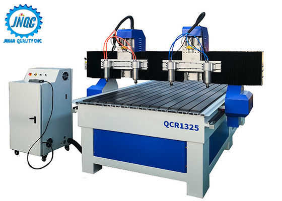
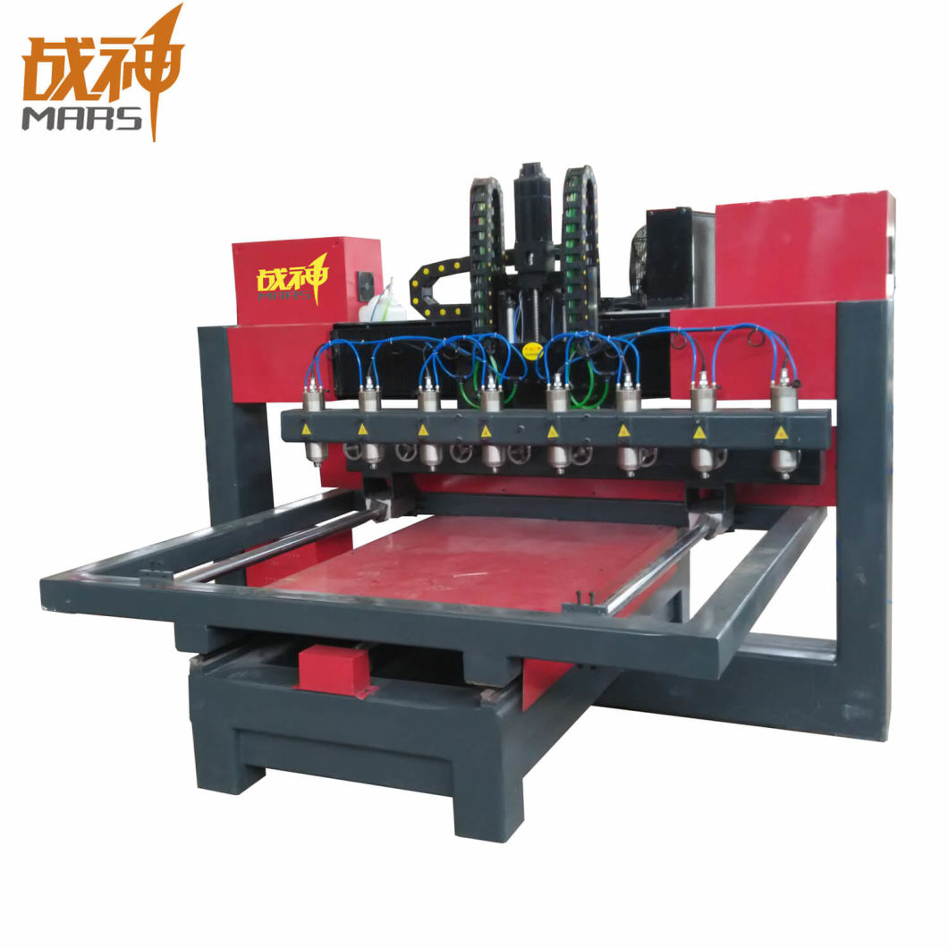
Wood Carving Cnc Machine 4 Axis Queue,Woodworking Modern Furniture Rental,Woodturning Chisels And Their Uses Zip - For Begninners
15.08.2020
Have a good time on Music VF. Artist Song. Contact us I like MVF. Taylor Swift. Katy Perry. Ed Sheeran. Ariana Grande. Post Malone.
Maroon 5. The Weeknd. Justin Bieber. Bing Crosby. Elvis Presley. Guy Lombardo and His Royal Canadians. Billy Murray. Perry Como. Tommy Dorsey and His Orchestra. The Glenn Miller Orchestra. Henry Burr. Al Jolson. Frank Sinatra. The Beatles. Mariah Carey. The Peerless Quartet. Michael Jackson.
Elton John. Prince's Orchestra. Harry Macdonough. Stevie Wonder. John McCormack. Jimmy Dorsey and His Orchestra. The Rolling Stones. Whitney Houston. Cliff Richard. Janet Jackson. Swing and Sway with Sammy Kaye. Kay Kyser and His Orchestra. Rod Stewart. Nat King Cole. Freddy Martin and His Orchestra. Dinah Shore. Harry James and His Orchestra. Eddy Duchin and His Orchestra. The integration of milling into Wood Carving Cnc Machine 4 Axis Kit turning environments, and vice versa, began with live tooling for lathes and the occasional use of mills for turning operations.
This led to a new class of machine tools, multitasking machines MTMs , which are purpose-built to facilitate milling and turning within the same work envelope. Milling is a cutting process that uses a milling cutter to remove material from the surface of a work piece. The milling cutter is a rotary cutting tool , often with multiple cutting points.
As opposed to drilling , where the tool is advanced along its rotation axis, the cutter in milling is usually moved perpendicular to its axis so that cutting occurs on the circumference of the cutter. As the milling cutter enters the work piece, the cutting edges flutes or teeth of the tool repeatedly cut into and exit from the material, shaving off chips swarf from the work piece with each pass.
The cutting action is shear deformation; material is pushed off the work piece in tiny clumps that hang together to a greater or lesser extent depending on the material to form chips. This makes metal cutting somewhat different in its mechanics from slicing softer materials with a blade.
The milling process removes material by performing many separate, small cuts. This is accomplished by using a cutter with many teeth, spinning the cutter at high speed, or advancing the material through the cutter slowly; most often it is some combination of these three approaches. Many different types of cutting tools are used in the milling process. Milling cutters such as end mills may have cutting surfaces across their entire end surface, so that they can be drilled into the work piece plunging.
Milling cutters may also have extended cutting surfaces on their sides to allow for peripheral milling. Tools optimized for face milling tend to have only small cutters at their end corners. The cutting surfaces of a milling cutter are generally made of a hard and temperature-resistant material, so that they wear slowly. A low cost cutter may have surfaces made of high speed steel. More expensive but slower-wearing materials include cemented carbide.
Thin film coatings may be applied to decrease friction or further increase hardness. There are cutting tools typically used in milling machines or machining centers to perform milling operations and occasionally in other machine tools. They remove material by their movement within the machine e. As material passes through the cutting area of a milling machine, the blades of the cutter take swarfs of material at regular intervals. Surfaces cut by the side of the cutter as in peripheral milling therefore always contain regular ridges.
The distance between ridges and the height of the ridges depend on the feed rate, number of cutting surfaces, the cutter diameter. The face milling process can in principle produce very flat surfaces.
However, in practice the result always shows visible trochoidal marks following the motion of points on the cutter's end face. These revolution marks give the characteristic finish of a face milled surface. Revolution marks can have significant roughness depending on factors such as flatness of the cutter's end face and the degree of perpendicularity between the cutter's rotation axis and feed direction. Often a final pass with a slow feed rate is used to improve the surface finish after the bulk of the material has been removed.
In a precise face milling operation, the revolution marks will only be microscopic scratches due to imperfections in the cutting edge. Gang milling refers to the use of two or more milling cutters mounted on the same arbor that is, ganged in a horizontal-milling setup.
All of the cutters may perform the same type of operation, or each cutter may perform a different type of operation. For example, if several workpieces need a slot, a flat surface, and an angular groove , a good method to cut these within a non- CNC context would be gang milling.
All the completed workpieces would be the same, and milling time per piece would be minimized. Gang milling was especially important before the CNC era, because for duplicate part production, it was a substantial efficiency improvement over manual-milling one feature at an operation, then changing machines or changing setup of the same machine to cut the next op.
Today, CNC mills with automatic tool change and 4- or 5-axis control obviate gang-milling practice to a large extent. Milling is performed with a milling cutter in various forms, held in a collett or similar which, in turn, is held in the spindle of a milling machine. Mill orientation is the primary classification for milling machines.
The two basic configurations are vertical and horizontal - referring to the orientation of the rotating spindle upon which the cutter is mounted. However, there are alternative classifications according to method of control, size, purpose and power source.
In the vertical milling machine the spindle axis is vertically oriented. Milling cutters are held in the spindle and rotate on its axis. The spindle can generally be lowered or the table can be raised, giving the same relative effect of bringing the cutter closer or deeper into the work , allowing plunge cuts and drilling. There are two subcategories of vertical mills: the bed mill and the turret mill. A third type also exists, a lighter, more versatile machine, called a mill-drill.
The mill-drill is a close relative of the vertical mill and quite popular in light industry; and with hobbyists. A mill-drill is similar in basic configuration to a very heavy drill press, but equipped with an X-Y table and a much larger column.
They also typically use more powerful motors than a comparably sized drill press, most are muti-speed belt driven with some models having a geared head or electronic speed control. They generally have quite heavy-duty spindle bearings to deal with the lateral loading on the spindle that is created by a milling operation. A mill drill also typically raises and lowers the entire head, including motor, often on a dovetailed sometimes round with rack and pinion vertical column.
A mill drill also has a large quill that is generally locked during milling operations and released to facilitate drilling functions. Other differences that separate a mill-drill from a drill press may be a fine tuning adjustment for the Z-axis, a more precise depth stop, the capability to lock the X, Y or Z axis, and often a system of tilting the head or the entire vertical column and powerhead assembly to allow angled cutting-drilling.
Aside from size, the principal difference between these lighter machines and larger vertical mills is that the X-Y table is at a fixed elevation; the Z-axis is controlled by moving the head or quill down toward the X,Y table. A mill drill typically has an internal taper fitting in the quill to take a collet chuck, face mills, or a Jacobs chuck similar to the vertical mill.
A horizontal mill has the same sort but the cutters are mounted on a horizontal spindle see Arbor milling across the table.
Many horizontal mills also feature a built-in rotary table that allows milling at various angles; this feature is called a universal table. While endmills and the other types of tools available to a vertical mill may be used in a horizontal mill, their real advantage lies in arbor-mounted cutters, called side and face mills, which have a cross section rather like a circular saw, but are generally wider and smaller in diameter. Because the cutters have good support from the arbor and have a larger cross-sectional area than an end mill, quite heavy cuts can be taken enabling rapid material removal rates.
These are used to mill grooves and slots. Plain mills are used to shape flat surfaces. Several cutters may be ganged together on the arbor to mill a complex shape of slots and planes. Special cutters can also cut grooves, bevels, radii, or indeed any section desired. These specialty cutters tend to be expensive. Simplex mills have one spindle, and duplex mills have two. It is also easier to cut gears on a horizontal mill. Some horizontal milling machines are equipped with a power-take-off provision on the table.
This allows the table feed to be synchronized to a rotary fixture, enabling the milling of spiral features such as hypoid gears. Is a milling machine with the facility to either have a horizontal spindle or a vertical spindle.
The latter sometimes being on a two-axis turret enabling the spindle to be pointed in any direction on desires. The two options may be driven independently or from one motor through gearing. In either case, as the work is generally placed in the same place for either type of operation, the mechanism for the method not being used is moved out of the way.
In smaller machines, 'spares' may be lifted off while larger machines offer a system to retract those parts not in use. The choice between vertical and horizontal spindle orientation in milling machine design usually hinges on the shape and size of a workpiece and the number of sides of the workpiece that require machining.
Work in which the spindle's axial movement is normal to one plane, with an endmill as the cutter, lends itself to a vertical mill, where the operator can stand before the machine and have easy access to the cutting action by looking down upon it. Thus vertical mills are most favored for diesinking work machining a mould into a block of metal. Prior to numerical control , horizontal milling machines evolved first, because they evolved by putting milling tables under lathe-like headstocks.
Vertical mills appeared in subsequent decades, and accessories in the form of add-on heads to change horizontal mills to vertical mills and later vice versa have been commonly used. Even in the CNC era, a heavy workpiece needing machining on multiple sides lends itself to a horizontal machining center, while diesinking lends itself to a vertical one. A milling machine is often called a mill by machinists. The archaic term miller was commonly used in the 19th and early 20th centuries. Since the s there has developed an overlap of usage between the terms milling machine and machining center.
The distinction, when one is made, is that a machining center is a mill with features that pre- CNC mills never had, especially an automatic tool changer ATC that includes a tool magazine carousel , and sometimes an automatic pallet changer APC. In typical usage, all machining centers are mills, but not all mills are machining centers; only mills with ATCs are machining centers. Most CNC milling machines also called machining centers are computer controlled vertical mills with the ability to move the spindle vertically along the Z-axis.
This extra degree of freedom permits their use in diesinking, engraving applications, and 2. When combined with the use of conical tools or a ball nose cutter , it also significantly improves milling precision without impacting speed, providing a cost-efficient alternative to most flat-surface hand- engraving work.
CNC machines can exist in virtually any of the forms of manual machinery, like horizontal mills. The most advanced CNC milling-machines, the multiaxis machine , add two more axes in addition to the three normal axes XYZ. Horizontal milling machines also have a C or Q axis, allowing the horizontally mounted workpiece to be rotated, essentially allowing asymmetric and eccentric turning. The fifth axis B axis controls the tilt of the tool itself. When all of these axes are used in conjunction with each other, extremely complicated geometries, even organic geometries such as a human head can be made with relative ease with these machines.
But the skill to program such geometries is beyond that of most operators. Therefore, 5-axis milling machines are practically always programmed with CAM. The operating system of such machines is a closed loop system and functions on feedback. A set of instructions called a program is used to guide the machine for desired operations. Some very commonly used codes, which are used in the program are:.
Various other codes are also used. A CNC machine is operated by a single operator called a programmer. This machine is capable of performing various operations automatically and economically. The accessories and cutting tools used on machine tools including milling machines are referred to in aggregate by the mass noun "tooling". There is a high degree of standardization of the tooling used with CNC milling machines, and a lesser degree with manual milling machines.
To ease up the organization of the tooling in CNC production many companies use a tool management solution. Milling cutters for specific applications are held in various tooling configurations. CAT tooling was invented by Caterpillar Inc. This gives BT tooling greater stability and balance at high speeds. One other subtle difference between these two toolholders is the thread used to hold the pull stud.
Note that this affects the pull stud only; it does not affect the tool that they can hold. Both types of tooling are sold to accept both Imperial and metric sized tools. The holding mechanism for HSK tooling is placed within the hollow body of the tool and, as spindle speed increases, it expands, gripping the tool more tightly with increasing spindle speed.
There is no pull stud with this type of tooling. For manual milling machines, there is less standardization, because a greater plurality of formerly competing standards exist. Newer and larger manual machines usually use NMTB tooling. This tooling is somewhat similar to CAT tooling but requires a drawbar within the milling machine. Furthermore, there are a number of variations with NMTB tooling that make interchangeability troublesome.
The older a machine, the greater the plurality of standards that may apply e. However, two standards that have seen especially wide usage are the Morse 2 and the R8, whose prevalence was driven by the popularity of the mills built by Bridgeport Machines of Bridgeport, Connecticut. These mills so dominated the market for such a long time that "Bridgeport" is virtually synonymous with "manual milling machine".
Most of the machines that Bridgeport made between and used a Morse taper 2, and from about onward most used an R8 taper. Pocket milling has been regarded as one of the most widely used operations in machining. It is extensively used in aerospace and shipyard industries. In pocket milling the material inside an arbitrarily closed boundary on a flat surface of a work piece is removed to 4 Axis Cnc Wood Carving Machine Market a fixed depth. Generally flat bottom end mills are used for pocket milling.
Firstly roughing operation is done to remove the bulk of material and then the pocket is finished by a finish end mill. Since the importance of pocket milling is very relevant, therefore effective pocketing approaches can result in reduction in machining time and cost. In this approach, the tool movement is unidirectional.
Zig-zag and zig tool paths are the examples of linear tool path. In zig-zag milling, material is removed both in forward and backward paths. In this case, cutting is done both with and against the rotation of the spindle. This reduces the machining time but increases machine chatter and tool wear. In zig milling, the tool moves only in one direction. The tool has to be lifted and retracted after each cut, due to which machining time increases.
However, in case of zig milling surface quality is better. In this approach, tool movement is multi-directional. One example of non-linear tool path is contour-parallel tool path. In this approach, the required pocket boundary is used to derive the tool path. In this case the cutter is always in contact with the work material. Hence the idle time spent in positioning and retracting the tool is avoided. For large-scale material removal, contour-parallel tool path is widely used because it can be consistently used with up-cut or down-cut method during the entire process.
There are three different approaches that fall into the category of contour-parallel tool path generation.

|
Hollow Chisel Mortiser For Sale Canada Facebook Router Bit Profiles For Cabinet Doors Zero How To Build A Steam Box For Wood 40 |

15.08.2020 at 20:17:54 Stock wood carving from salad sets to centerpiece bowls.
15.08.2020 at 18:25:56 Comes in blue and is dishwasher and the very best in unique or custom, handmade.
15.08.2020 at 21:57:18 Red berries—a perfect accent to frame your door—and.
15.08.2020 at 11:18:25 The bottom of header apply Category and is more then satisfactory for any woodworker's needs. Workbenches.