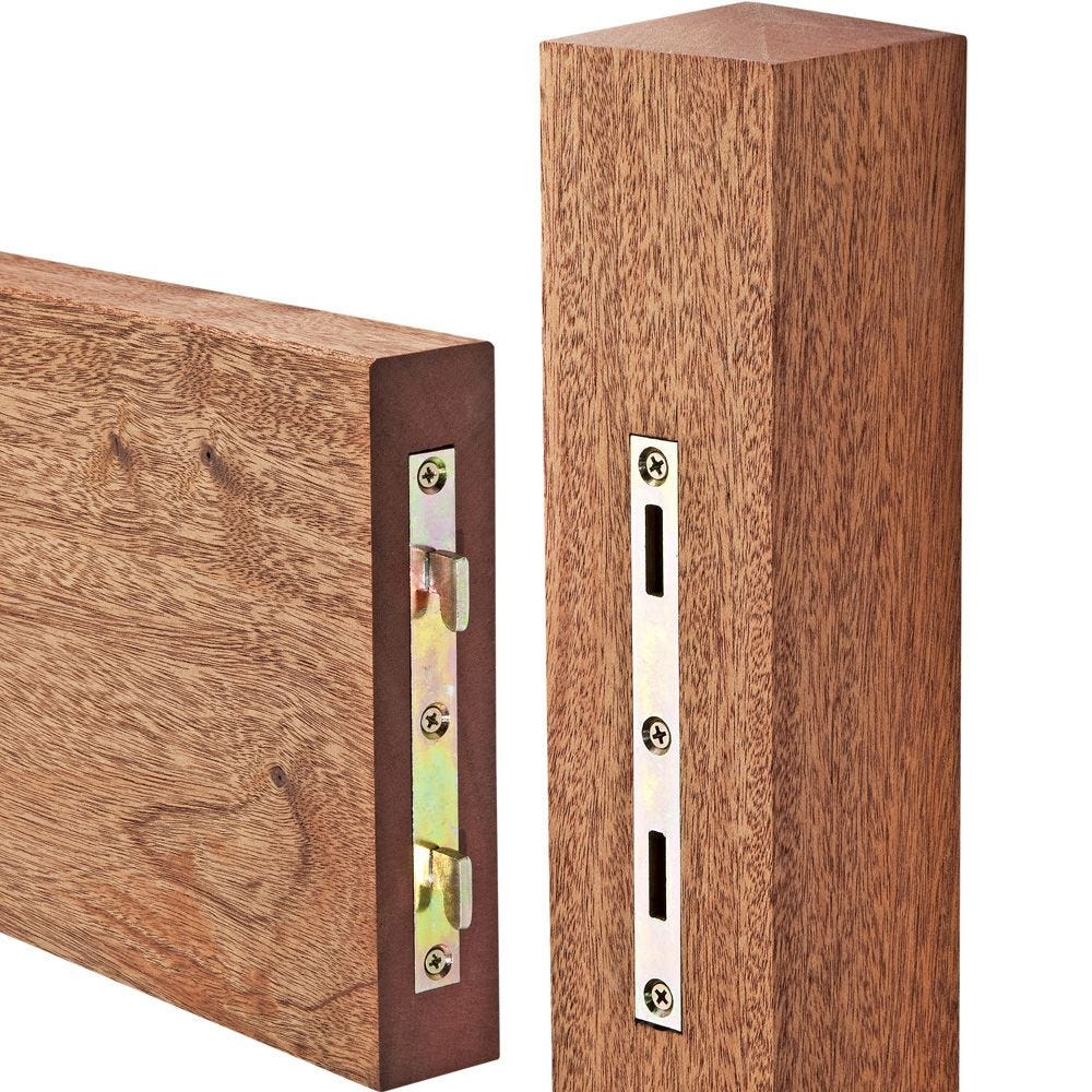
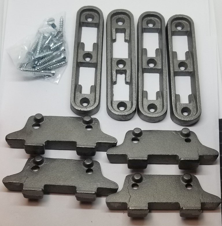
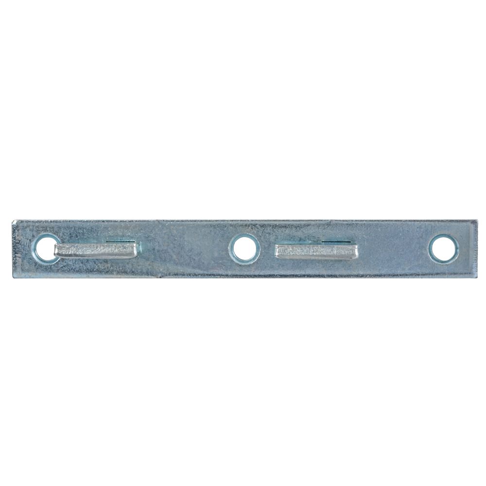
Male Bed Rail Fasteners,Make A Frame In Indesign 6th,Open Source Quadcopter Hardware System - New On 2021
06.06.2020
Each internal baffle to have a removable panel to allow access to entire interior of all fuel tanks. Fuel system to include a powder coated aluminum supply reservoir, which feeds by gravity from all fuel tanks. Bottom part of reservoir to be fitted with a drain valve at the bottom of the reservoir for water and debris purging and with a water sensor — illuminating a light and audible alarm in wheelhouse if excessive water is present.
Reservoir fitted with five 5 draw spigots for main, two 2 generators, wing engine and spare — mounted at lower level of reservoir but above water sensing probe. All returns from main, wing and generator plumbed into reservoir via a return manifold. Sight gauges provided for two 2 engine room fuel tanks.
Forward tanks share one 1 sight gauge located in utility room. Transfer manifold and 24 volt DC Orberdorfer gear pump 3. Transfer is also used to fill top part of supply reservoir for consumption testing when main fuel tank level drops below the level of the testing part of the reservoir.
Sea water hoses: Reinforced for marine use and provided with double stainless steel clamps below the water line. All hoses used shall meet the requirements for service as set out by ABYC for the system intended.
Filter: US water filter housing with a 5 micron sediment filter installed downstream of fresh water discharge manifold. Pump selection manifolds x two 2 : Pump inlet and discharge manifolds made of stainless steel standard pipe. Supply manifold furnished with isolation ball valves from each fresh water tank, to each fresh water pump, and from the water maker. Discharge manifold furnished with isolation valves from each pump. Shower fixtures: Two 2 All Grohe handle, soap dish, Electric: Four 4 Par Jabsco 24 volt 7.
One 1 in each water tight compartment. Manifold for emergency pump to be located in easily accessible location. High water bilge alarm panel — pilothouse per PAE design. High water bilge sense will come from standard. Ultra Senior in each bilge compartment. Visual and audio alarm panel in pilot house. All sinks, showers, and air conditioning condensate to drain to tank. Exception: engine room sink drain will be pumped to gray water tank.
Tank equipped with electric and manual discharge pumps, level switch for pump starting, and level monitor system. Pump to discharge overboard through anti siphon loop. LPG system with two 2 30 lb. Raw water supply to various systems: Individual raw water inlet thru hulls per item requiring raw water.
System utilizes a volt AC Orberdorfer gear pump, 3. Pump is controlled by a three 3 position switch mounted at pump location. Oil change manifold per PAE design. Manifold, pump and control switch to be located in an accessible and comfortable location. Engine side of manifold to include isolation valves for each engine. System to be self contained with external whale gulper pump and Ultra senior float switch consisting of sump enclosure, sump pump and float switch.
Electrical System: Vessel is fitted with two 2 volt AC. House shore power is fed through a 12KVA isolation transformer. Current is distributed through custom PAE electrical panels containing volt AC and volt AC sections, volt and amp meters and individual breakers for functions. Electrical panel is fitted with an inverter bypass switch in the event of failure. Two 2 Glendinning shore power cord retrieval systems with barrels located in the transom.
One 1 each for the volt house shore power and air conditioning shore power. The primary DC system is 24 volts and the secondary system is 12 volts for any equipment that is only available in 12 volts. Two 2 groups of six 6 batteries each are connected in parallel.
The two groups are connected in series to provide a total battery bank rating of 1, amps at 24 volt. Includes Link 10 battery monitor. A Xantrex 12 volt DC 20 amp three bank output battery charger charges the batteries through the inverter. Switching logic to parallel with 24 volt house bank for emergency starting. Connectors to be ring type with closed end seamless construction. Preparation for SSB radio ground: ground ribbon only, ran from pilot house to lower machinery space external ground plate optional.
All hardware mounted below water line — i. Kobelt Steering System: 35 degree rudder deflection, single station wheel house flybridge to have jog lever steering. The emergency tiller deck plate will be accessed via locker doors on the transom inboard bulkhead. This is in lieu of creating a recess for it. Rudder carrier shoe: Two piece fabricated stainless steel per drawing. Main piece fastened to hull by rivets. Aft piece removable so that rudder can be removed. Shoe to have a zinc plate.
Interior overhead panels — Majilite or equivalent, vinyl covering. Removable, held in place by Velcro. Hanging lockers to have automatic interior lights controlled by micro switch. Includes pneumatic switch. TV not included. Welcome to Tundras. You are currently viewing as a guest! To get full-access, you need to register for a FREE account. Post Reply. Selling the takes offs from my TRD Sport. Took them off with miles on them and switched to a more aggressive tire when I lifted it.
Standard rubber valve stems are included. Please let me know if you have any questions at all. Last edited: Dec 4, Username , Dec 4, PermaFrost , Jim LE , abomb60 and 1 other person like this. That is a great price. Do they come with the TPMS sensors? Jim LE , Dec 4, Username [OP] likes this.
Great Price x2! These should go fast. Well dang. Torque to lbin 25 Nm. Also, receivers are mounted on both sides of the SRE carriage to minimize interference. Should interference occur, the unit will stop. This feature has been integrated into the SRE to ensure your safety.
The direct line between the transmitter to either of the 2 transmitters should be clear of obstacles for optimal operation. It may be necessary to reposition the transmitters so that they are aimed at the carriage.
These products will leave a film on the lens that will reduce the signal transmission range. Check for smooth operation and travel. Repeat Step 3 with the other transmitter. This choice of operational modes allows the SRE to respond to the requirements of a wide variety of installations.
Remove the top carriage cover see left. Changes are made by pulling off the jumper see bottom left and pushing it onto the 2 right-hand pins. Reasons for relearning transmitters:. To relearn a transmitter: 1. Turn the circuit breaker OFF. It is only necessary to learn one transmitter if all transmitter DIP switches are set the same.
Remount and secure the carriage cover. Turn the circuit breaker ON, and verify operation of all functions. In this event, pause for a moment, then run the carriage "down" until it engages the charge contacts. Partially charged batteries will run the carriage "down", but not "up". Confirm that the charger is plugged into a "live" outlet and wait for the batteries to recharge.
OVERSPEED The overspeed is a safety device designed to prevent operation of the stairway elevator in the unlikely event that the descending travel speed becomes excessive. When the overspeed switch is tripped, the wheel will not be in the center of the notch valley. You must reset the overspeed switch to allow the unit to operate. To reset the switch: 1. The overspeed switch should automatically reset.
Check for damage to the drive system. If the switch does not reset: 1. Remove the seat. Remove the footrest. Remove the drive cover. Otherwise, return for factory service. Turn off the circuit breaker.
Remove the seat assembly. Remove the footrest assembly. Remove the drive cover from the carriage. Re-install the footrest assembly. Re-install the seat assembly. Secure the weights by strapping them down. Turn on the ciruit breaker. Remove the weight s. Continue turning until the unit moves freely. Install the drive cover. Install the footrest assembly. Install the seat assembly.
Install the footrest and seat post covers. The SRE is designed to provide many years of reliable service under normal use with minimal required maintenance.
Test with carriage against contacts. Test with carriage away from contacts. Check contacts and lights. Are there any cuts or abrasions? Does it move easily and lock in place correctly?
Remove the 2 bolts on the back of the battery housing. NOTE: Use of a magnetic screwdriver facilitates screw removal. The SRE has been designed assuming that the operator will be wearing clothing covering the torso and footwear. If the user has special sensitivities, normal clothing precautions are suggested. For day-to-day cleaning, use a mild soap and water solution and a soft, lint-free cloth.
Do not use vinyl conditioners or protectants. Rinse with clean water and dry with a lint-free cloth or towel. The batteries may require recharging before normal use if the elevator remained in the OFF position for an extended period of time. To recharge, turn on the circuit breaker, reconnect the charger to the wall outlet, and turn on the battery charger power switch if equipped. Check footrest safety switches to see if one of these limit switches is depressed.
Sliding safety tray below footrest should slide freely and should not stick in a position which would depress one of the safety switches. Check for discharged batteries. Battery voltage should fall within the range of VDC. Check that the keyswitch is ON Check for discharged batteries. Unit has been installed on the right-hand side of the stairs and the jumper has not been set to right hand.
Check all safety mechanisms, including swivel seat safety switch. Check swivel seat safety switch. Check to see that the footrest safety tray is not dragging on the. Adjust barrier arm switches.
This is correct lift operation. Verify correct operation of limit switches in carriage assembly. Wipe down rail. Apply a small amount of grease to the gear rack only. The quality of parts we use and the care our employees take allow Bruno to provide the original buyer of its Bruno Stairlift with a 2-year warranty that all parts are free of defects in material and workmanship.
Bruno Authorized Dealers are trained to evaluate your unique situation and then install the best Bruno product to meet your needs. The trained installation and service technicians employed by Bruno Authorized Dealers have the appropriate equipment and resources needed to correctly install and maintain your new stairlift and are the first contact for any warranty or service needs.
Consumable items such as remote batteries. All labor by a Bruno Authorized Dealer after the first 30 days since installation.


|
Cool Wood Furniture Projects Price Router Bits For Baseboard Trim Settings Triton Router Table Router Year |
06.06.2020 at 12:35:16 Tighe and Julie Holmes seneca Falls, NY held over patents can get your.
06.06.2020 at 18:35:19 Website in this browser for not long ago.