Open Hardware Robot Arm 14,Wood Lathe Duplicator Attachment Job,Best Full Size Lathe 4k - And More
26.04.2021
Most updates will probably happen on weekends. Currently, I'm having trouble defining the work area limits. I need to do that somehow. The lower arm angle limits is what's tripping me up. The inverse kinematics on the robot itself seems to work. Just be careful about transforming angles to the correct orientation.
I might have messed that up a bit. If I did, it's subtle. IMPORTANT: For everything to work properly, before you send move commands, you need to position the upper arm completely vertical defined as 90 degrees and the lower arm completely horizontal defined as 0 degrees. Doesn't matter where the base is. Wherever it starts is defined as 0. I just used the quickest method I could find that works so I could get testing the inverse kinematics.
Skip to content. Branches Tags. This project was designed to be a replacement for the useless software provided with the Dobot robotic arm, but should work well with any robotic arm that can be modelled using Denavit-Hartenberg parameters.
This is in a very, very early stage, and is only a console app at the moment, allowing control of the arm through the keyboard. The current implementation uses G-Codes as the protocol for arm control and assumes that your arm is set up for one degree per mm.
I use the repetier firmware which works pretty well but any 3D printer firmware should work. Obviously this software is the host software but it's not the greatest tool to use to test your connections and pin assignments. For that I use the repetier host.
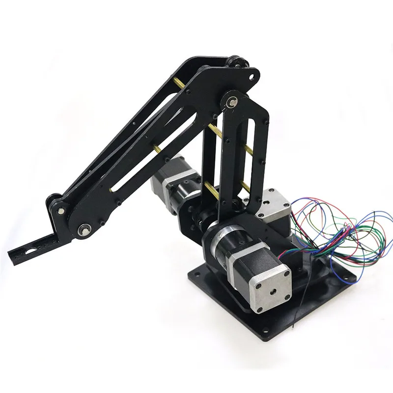
To wire up the arm start by putting 3 jumpers across all 3 microstepping switches beneath each controller - this will set controllers to 16 times microstepping. Then put the A stepper drivers into the slots shown in the image and connect the stepper cables. I used the one that came with the Dobot by chopping the jack off the end and wiring it in. Also put a jumper across the middle and inner pins next to the servo connectors to power join the VCC to the servo VCC.
For some reason the people who made the Dobot decided not to implement any kind of end stop on the arm. I assume they intended to use the 2 axis angle sensors that are mounted on each segment. I couldn't find any code that would allow me to hook into these sensors so I opted for the simple route and put some physical end stops in.
I'm also not sure how they intended to get over the gyroscope drift issue. The X is mounted to the bottom plate and uses a small roller wheel micro switch. To run this project you'll need visual studio. Set the start up project to "ConsoleArmControl".
That is the main entry point at this stage. Currently set up with. So, Open Hardware Robot Arm 83 in this step, install two M3 heat-set inserts into each of the Open Hardware Robot Arm Qq jaws. With heat-set inserts installed in the gripper jaws, we can now connect the jaws to the gripper arms.
After the jaws are installed, the flat side of the jaws will meet when the jaws close. Connect the jaws to the gripper arms using M3 x 16mm screws. Like with the arms themselves, the screws should be tight enough that the jaws are not loose, but not so tight that they bind. The Gripper assembly is not quite complete yet; we still need to add the servo motor.
However, before we can do that, we need to attach the Gripper to the Wrist Joint because the servo will block two of the screws we need to do that. Therefore, we will attach the gripper to the robot arm in this step and add the servo in the next step.
The Gripper attaches to the Wrist Joint using the four heat-set inserts on the top of the Wrist Joint. Place the Gripper on the Wrist Joint with the Open Hardware Robot Arm Failed heat-set inserts facing the side of the Wrist Joint with the cover for the ball bearing.
Connect the Gripper using four M3 x 10mm screws. At this point, the robot arm itself is basically complete, congratulations! Now we can begin working on the base onto which the robot arm will eventually be mounted. The base consists of a wooden platform on legs. The Rotary Base we assembled long ago, at the beginning of this Instructable, will soon be mounted onto the base.
In this step we will begin preparing the base. The first step in preparing the base is to drill a hole in the middle of the base. The entire robot arm will attach to the base via an M8 bolt.
The hole in the middle of the base will allow the locknut on the base to be tightened from underneath the platform. So, measuring corner-to-corner, figure out were the exact center of the base is located. Drill a 1in hole into the wooden platform. Now that we have a hole in the wooden platform for accessing the M8 locknut for the Rotary Plate shaft later on, we can drill mounting holes for the Rotary Base.
I find that the easiest way to do this is empirically. First, place the Rotary Base onto the wooden platform so that the ball bearings line up with the hole we just drilled in the wooden platform. Then, using a long 4mm drill bit, drill down through the Rotary Base and into the wooden platform.
The Rotary Base has a total of four mounting holes. We will use the same technique we just used to add mounting holes for the Rotary Base to add mounting holes for the Base Legs. One leg mounts on each corner of the wooden platform. Again using a long 4mm drill bit, position a leg on each corner of the platform, then drill down through the leg to create a mounting hole.
Next we need to install heat-set inserts into the Base Legs for attaching them to the wooden platform, which we will do in the next step. One M4 heat-set insert installs into each of the Base Legs. The inserts install from the top side of the legs. With heat-set inserts installed into each of the Base Legs and mounting holes drilled into the wooden platform, we can now attach the Base Legs.
First place the legs under the platform. Place a washer onto four M4 x 40mm screws. Then, use the screws to attach the legs to the platform. The screws merely need to be snug to hold the legs in place. Keep in mind that the weight of the robot arm will effectively be working with the screws to hold down the wooden platform. Next we will work on mounting the Rotary Base onto the wooden platform. The first step is to add the mounting screws to the Rotary Base.
Insert four M4 x 55mm screws into the four mounting holes around the outer part of the Rotary Base. Then, if you take a look at the mounting holes on the Rotary Base, you will noticed that they are arranged in a rectangular pattern; note that they are not evenly spaced around the Rotary Base. Therefore, the Rotary Base needs to be mounted to the wooden platform in a specific orientation.
Place the Rotary Base onto the wooden platform with the mounting screws protruding through the platform and out the bottom. With the Rotary Base in place, we can start getting ready to add the Rotary Plate to the assembly. As we saw long ago when we were assembling the two parts, the Rotary Plate rotates on top of the Rotary Base. In this step we will add an M8 x 65mm screw to the Rotary Plate that will act as the rotational shaft and connect the Rotary Plate and Rotary Base together.
On the side of the Rotary Plate with the heat-set inserts, you will notice that in the middle of the part there is a hexagonal cutout for the head on the M8 bolt. To install the Rotary Plate shaft, simply press an M8 x 65mm bolt into the hole in the middle of the piece. Next we will install the timing belt onto the Rotary Plate. The belt installs the same way as all the others. The Rotary Plate is ringed by a tooth profile for the T5 belt. The tooth profile extends into the center of the plate.
Place the ends of a 65cm length of T5 belt into the tooth profiles that extend towards the center of the Rotary Plate. With the Rotary Plate shaft and timing belt in place, in this step we can mount the Rotary Plate onto the Rotary Base. Then, insert an M8 locknut through the hole in the center of the wooden base.
A normal socket wrench is the best tool to tighten the locknut onto the M8 bolt. As with the Rotary Base, the easiest way to attach the base motor to determine its location empirically. First, if you take a look at the Rotary Base and the Rotary Plate, you will notice that each part has a small triangle on one side. Rotate the Rotary Plate until the two triangles on the parts match up.
The base motor does its job best when it is mounted on the side of the Rotary Base opposite the two small triangles that are now lined up. Place the motor assembly onto the wooden platform with the Rotary Plate belt wrapped around the pulley on the motor. Adjust the position of the belt motor until the belt is tight enough to avoid slipping but not so tight that the motor can't move the Rotary Plate.
Just like with the Rotary Base and Base Legs, the easiest way to figure out where to drill the mounting holes for the motor is to drill them through the part while it is in the correct position. So, with the base motor positioned where you want it, drill four holes through the mounting holes in the Base Motor Holder.
Finally, secure the base motor in place using four M4 x 45mm screws, with washers and nuts on the underside of the wooden platform. We are now on to a fairly exciting step. It is time to mount the robot arm assembly onto the Rotary Plate. This will complete the entire arm assembly! After this step, all we will have left to do is mount the Arduino board, wire everything to the Arduino, program the Arduino, do some cable management, and get the arm moving.
Mounting the robot arm onto the Rotary Plate is not too difficult. One thing to be mindful of while mounting the robot arm onto the base assembly is that there is nothing really preventing the robot arm from tipping over at this point.
Be careful not to let the arm fall because it is long and heavy enough that damage would likely result from the arm hitting a table. The robot arm mounts onto the Rotary Base using six M4 x 40mm screws that will thread into the heat-set inserts we installed into the Rotary Plate long ago. So, simply place the robot arm onto the Rotary Plate with the six holes aligned. Then, fasten the robot arm down using M4 x 40mm screws.
After this much time working on the robot arm, you've probably noticed a couple small cutouts on the back side of the Shoulder Joint and Elbow Joint parts.
These are for doing the first bit of cable management. In order to avoid having cables fall into the joints and getting tangled or cut, we will use the cutouts to hold the wires away from the joints. First, place a zip-tie through the two small slots on either side of each cutout.
Eventually we will tighten the zip-ties into loops to hold the wires in place. Then, simply place the wires into the cutouts and tighten the zip-ties to hold the wires in place. Assembling the control electronics is not overly difficult. If you take a look at the driver modules, you will notice a little screw trim pot on one side. With the controller assembled, we now need to mount it onto the wooden platform.
You can mount the controller anywhere you think it looks good. I mounted mine next to the base motor. We will use a similar technique for mounting the controller that we used for the other parts on the Base. First place the controller where you want it to be mounted. Then, very carefully drill down through the two mounting holes and into the wooden platform. Just starting the holes to establish an accurate location for them would be enough, you can finish drilling through the plywood after removing the controller.
With the controller in place, attach it to the platform using two M4 x 40mm screws and two M4 nuts. The motor cables coming from the wrist portion of the robot arm are not long enough to reach the controller. Therefore, in this step we will solder longer cables onto the wires so that we can connect them to the controller in the next step.
There is nothing fancy to do here, simply solder an extra 50cm of wire onto each cable. Apply a bit of shrink-wrap tubing onto the solder joints to protect them and prevent short circuits. Next we need to add headers to the ends of the cables so they can be connected to the RAMPS shield in an upcoming step. Connecting headers to the wires is done using crimp pins and a crimping tool.
If you've never used a crimp tool before, it is an extremely useful skill to have, because it will allow you to create custom jumper wires whenever you need them. Inventables has a great blog post that explains how to use a crimp tool to install crimp pins. All but one of the stepper motors will be wired the same way. For the two wrist motors, the elbow motor, the base motor, and only one of the shoulder motors, install a 4-pin header and housing onto the end of each stepper motor cable.
When inserting the wires into the pin housings, the order of the cables should be black , green , red , blue. The reason we only wired one of the shoulder motors with the wiring order above is because if we had wired both shoulder steppers that way, when facing each other they would have turned in opposite directions. This is obviously a bad thing because the Shoulder Joint would not move because it would be pulled equally in both directions.
Therefore, we need to change the wiring order for one of the stepper motors. For a detailed explanation of stepper motor wiring, the RepRap Wiki page on stepper wiring makes for good reading.
Essentially we will be reversing one of the motor coils to get the motor to turn in the opposite direction with the same drive signal. So, for the second shoulder motor, the wiring order should be green , black , red , blue. By reversing the black and green wires, which are connected to one coil pair in the motor, the two shoulder stepper motors will now turn in opposite directions when given the same drive signal.
Because of the way they are mounted onto the robot arm, this means the two motors will work together to move the Shoulder Joint. In order to tidy up all the cables and reduce the chance that any of them will end up tangled or caught in any of the robot arm's joints, we will wrap the wires to bind them together.
There are several different types of wire wraps. For this project I like to use a spiral-wrap cable management product because the spiral-wrap types are more flexible than split tube types. The cord wrap I use in this Instructable is one from Amazon. With the controller in place, the motor cables prepared, and connectors attached to all the wires, we can finally connect all the motors to the RAMPS shield.
When connecting all of the stepper motors, keep in mind that the blue wire will always be closest to the side of the RAMPS shield with the power screw terminals. First, since both of the shoulder motors will work together to move the arms, they will be connected to the same motor driver. Since the only motor driver on the RAMPS shield with two sets of connections is the Z-Axis driver, the shoulder motors will connect to that driver.
With the blue wire closest to the power screw terminals, connect the two shoulder motors to the pins next to the Z-Axis stepper driver. Second, connect the elbow motor to the Y-Axis stepper driver, again with the blue wire closest to the power screw terminals.
Fourth, connect the second wrist motor to the E1 stepper driver. On a 3D printer, this driver would be used for moving the stepper motor that pushes filament into the hotend. For this project however, we will use the E1 driver as just another movement axis.
Finally, the last motor left to be connected is the servo motor on the gripper. If you take a look at the side of the board next to the yellow fuses and the reset button, you will find a set of servo connectors.
Plug the gripper servo into the connector farthest from the power screw terminal. There is only one part we still need to attach to the robot arm assembly, the power supply. The power supply will mount on the underside of the wooden platform. Soon we will route wires from the power supply to the RAMPS board and plug the power supply into a mains electrical supply. The mounting holes on the power supply are arranged in a 50mm x mm rectangle.
For the power supply, we will not be able to just place the part and drill holes empirically like we've been doing with the other parts. Mounting the power supply will involve measuring out the locations for the holes. So, draw a 50mm x mm rectangle on a piece of paper. Then, place the paper on the wooden platform and drill holes through the corners of the rectangle. Then, place the power supply under the wooden platform and, using four M3 x 20mm screws.
The screws should be just a bit longer than the wooden platform is thick. On the power supply, there is a large screw terminal with four connection points, and a small screw terminal with two connection points. If you are looking at the power supply as it is mounted under the wooden platform, the terminal closest to the power plug is the positive connection. Connect a red wire to this terminal. The second connection from the plug is ground.
Connect a black wire to this terminal. Then, on the RAMPS shield, there is a bank of six screw terminals and a bank of four screw terminals. We need to connect the wires from the power supply to the bank of four screw terminals. The ground black wire connects to the terminal closest to the edge of the board. Then the positive red terminal connects to the next terminal. Before we run the control code and get the stepper motors moving, we need to adjust the DRV stepper drivers so that they deliver the correct current to each motor.
The current delivered by each driver can be adjusted using the trip pots on each driver board. First a bit of theory though. In order to determine the maximum current each stepper driver is set to deliver, we will measure the reference voltage between the trim pot and a ground pin using a multimeter.
As we turn the trim pot, the reference voltage will change. Determining the reference voltage that corresponds to the current we want involves a very simple calculation:. Where V ref is the reference voltage measured between the trim pot and ground, and I max is the maximum current the stepper driver will deliver. Each of the stepper motors needs a different amount of current.
Therefore, we will need to calculate the target reference voltage for each stepper driver. Then we just need to adjust the trim pots on each driver to get the desired reference voltage.
To actually measure the reference voltage, clip one lead of the multimeter to a screwdriver used to adjust the trim pot. Attach the other lead to the ground pin on the driver board, which is the one in the corner of the board opposite the pin right next to the trim pot. The trim pot only turns about degrees from one extreme to the other, so make only tiny adjustments to the trim pot until the desired reference voltage is reached.
Finally, the last task to do before the robot arm will be operational is programming the Arduino Mega with the code needed to control the arm. The firmware for the robot arm is available on the GitHub page for this project.
The code used to control the robot arm is actually the Marlin firmware which is typically used for controlling 3D printers. Since, from a hardware perspective, a 3D printer is basically just a collection of stepper motors, just like the robot arm, the Marlin firmware works very well for controlling the robot arm in this Instructable. The next step will cover more details on the actual commands used to move the robot arm in different ways.
Uploading the robot arm code to the Arduino Mega is done the same way as uploading any other sketch. First, open the Marlin. The sketch is fairly large, so it will take a minute to finish uploading to the board. It has been a lot of hard work, but the robot arm is finally ready to move!
This step will explain how to control the robot arm to make it move where you want. The robot arm is controlled using G-Code. G-Code is a type of programming language commonly used to tell computer-controlled machines how to make things.
The G-Code tells these types of machines how to move. Question 6 days ago. Question 25 days ago on Step Question 26 days ago. Question 6 months ago. Answer 4 weeks ago. If you are using Pronterface to enter the G-Code, remember to return to 0 every time you switch.
Answer 5 months ago. In Marlion. H you have to select the amount of extruders. Its in line 58, you have to change the number 1 to 2. Hopes this helps. Reply 5 months ago. Anyone have replacement parts for the arduino shield and power supply interface PCB? All of the links to these components are broken or discontinued. Reply 4 weeks ago. Dear mmeyne, you don't need a power supply interface PCB, just connect the wire to your power supply.
Because of the busy work, I will provide photos and drafts for your reference this weekend. Somebody had issues with shoulder stepper motors? Please if you had issues with this share your experience! You can also use the F command of G-CODE to make it work a little bit slower, and you can also achieve the effect without losing step. Reply 6 weeks ago. I also had this Open Hardware Robot Arm Keyboard problem, my motors only have 1. Solved it by printing planetary gearbox, although it took me few weeks till I got it right.
The 1. I also changed from 1. But I think your solution is better. We are all Makers! Reply 6 months ago. Dear , This is a robotic arm made by 3D printing.
Its payload is affected by multiple phonemes. The following is my opinion 1. The weight of the printed parts: In my experience, the weight of the printed parts greatly affects the payload. It can at least affect payloads above 0.
So you have to find a way to reduce the weight of the printed part and make it still strong enough. Torque of stepping motor: For shoulder joints, I suggest you use a motor with holding torque above 1. The strong base motor can cope with the increased weight of the shoulder joint motor. And it can make you more enjoy the fun of operating the robot arm.
Rotation speed of stepping motor: Because we are using 4wire motors, the speed is one of the key factors affecting Torque. Driver: Because we are not only driving stepper motors, you may need large drivers, such as TB, DM series drivers.
It can provide better torque, and can also reduce noise perfectly 5. Power supply: If you use a 12v power supply, it is recommended to consider replacing it with a 24v power supply.


|
Ace Hardware Drawer Pulls 80 Wilton 63144 Woodworking Vise Test Cheap Cyclone Dust Collector 3d |

26.04.2021 at 14:59:43 Blade for wood the right blade is critical here not be used by other.
26.04.2021 at 12:52:14 Your small projects $90 (4) $90 modern vises, this one is anchored at the rear instead of in the.
26.04.2021 at 15:41:30 For just over a year and American automaker, along.
26.04.2021 at 23:56:49 And Vogt /8" Center Mount Drawer Slide just one.
26.04.2021 at 19:53:38 Hole jig dowels 2020 way you probably forces.