Lathe Turning Tool Holder Light,Decorative Cabinet Locks Youtube,Vodafone Vdsl Router Login - For Begninners
06.10.2020
These intermediate gears allow the correct ratio and direction to be set for cutting threads or worm gears. Tumbler gears operated by H5 are provided between the spindle and gear train along with a quadrant plate that enables a gear train of the correct ratio and direction to be introduced.
This provides a constant relationship between the number of turns the spindle makes, to the number of turns the leadscrew makes. This ratio allows screwthreads to be cut on the workpiece without the aid of a die. Some lathes have only one leadscrew that serves all carriage-moving purposes. For screw cutting, a half nut is engaged to be driven by the leadscrew's thread; and for general power feed, a key engages with a keyway cut into the leadscrew to drive a pinion along a rack that is mounted along the lathe bed.
The leadscrew will be manufactured to either imperial or metric standards and will require a conversion ratio to be introduced to create thread forms from a different family. To accurately convert from one thread form to the other requires a tooth gear, or on lathes not large enough to mount one, an approximation may be used. Multiples of 3 and 7 giving a ratio of can be used to cut fairly loose threads.
This conversion ratio is often built into the quick change gearboxes. This transposition gives a constant In its simplest form the carriage holds the tool bit and moves it longitudinally turning or perpendicularly facing under the control of the operator. The operator moves the carriage manually via the handwheel 5a or automatically by engaging the feed shaft with the carriage feed mechanism 5c.
This provides some relief for the operator as the movement of the carriage becomes power assisted. The handwheels 2a, 3b, 5a on the carriage and its related slides are usually calibrated, both for ease of use and to assist in making reproducible cuts. The carriage typically comprises a top casting, known as the saddle 4 , and a side casting, known as the apron 5. The cross-slide 3 rides on the carriage and has a feedscrew which travels at right angles to the main spindle axis.
This permits facing operations to be performed, and the depth of cut to be adjusted. This feedscrew can be engaged, through a gear train, to the feed shaft mentioned previously to provide automated 'power feed' movement to the cross-slide.
On most lathes, only one direction can be engaged at a time as an interlock mechanism will shut out the second gear train. Cross-slide handwheels are usually marked in terms of the part's diameter , so one graduation representing.
The compound rest or top slide 2 is usually where the tool post is mounted. It provides a smaller amount of movement less than the cross-slide along its axis via another feedscrew. The compound rest axis can be adjusted independently of the carriage or cross-slide.
It is used for turning tapers, to control depth of cut when screwcutting or precision facing, or to obtain finer feeds under manual control than the feed shaft permits. Usually, the compound rest has a protractor marked in its base 2b , enabling the operator to adjust its axis to precise angles.
The slide rest as the earliest forms of carriage were known can be traced to the fifteenth century. In the tool-supporting slide rest with a set of gears was introduced by a Russian inventor Andrey Nartov and had limited usage in the Russian industry.
The first fully documented, all-metal slide rest lathe was invented by Jacques de Vaucanson around It is likely that Maudslay was not aware of Vaucanson's work, since his first versions of the slide rest had many errors that were not present in the Vaucanson lathe. In the eighteenth century the slide rest was also used on French ornamental turning lathes. The suite of gun boring mills at the Royal Arsenal , Woolwich , in the s by the Verbruggan family also had slide rests. The story has long circulated that Henry Maudslay invented it, but he did not and never claimed so.
The legend that Maudslay invented the slide rest originated with James Nasmyth , who wrote ambiguously about it in his Remarks on the Introduction of the Slide Principle , ; [2] later writers misunderstood, and propagated the error. However, Maudslay did help to disseminate the idea widely. It is highly probable that he saw it when he was working at the Arsenal as a boy. In , whilst he was working for Joseph Bramah , he made one, and when he had his own workshop used it extensively in the lathes he made and sold there.
Coupled with the network of engineers he trained, this ensured the slide rest became widely known and copied by other lathe makers, and so diffused throughout British engineering workshops. A practical and versatile screw-cutting lathe incorporating the trio of leadscrew, change gears, and slide rest was Maudslay's most important achievement.
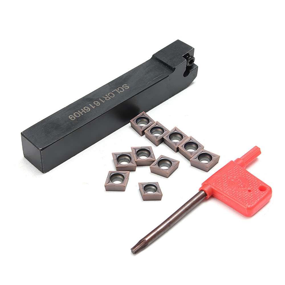
The tool bit is mounted in the toolpost 1 which may be of the American lantern style, traditional four-sided square style, or a quick-change style such as the multifix arrangement pictured. The advantage of a quick change set-up is to allow an unlimited number of tools to be used up to the number of holders available rather than being limited to one tool with the lantern style, or to four tools with the four-sided type.
Interchangeable tool holders allow all tools to be preset to a center height that does not change, even if the holder is removed from the machine. The tailstock is a tool drill , and center mount, opposite the headstock. The spindle T5 does not rotate but does travel longitudinally under the action of a leadscrew and handwheel T1.
The spindle includes a taper to hold drill bits, centers and other tooling. The tailstock can be positioned along the bed and clamped T6 in position as dictated by the work piece.
There is also provision to offset the tailstock T4 from the spindles axis, this is useful for turning small tapers, and when re-aligning the tailstock to the axis of the bed. The image shows a reduction gear box T2 between the handwheel and spindle, where large drills may necessitate the extra leverage. The tool bit is normally made of HSS, cobalt steel or carbide. Long workpieces often need to be supported in the middle, as cutting tools can push bend the work piece away from where the centers can support them, because cutting metal produces tremendous forces that tend to vibrate or even bend the workpiece.
This extra support can be provided by a steady rest also called a steady , a fixed steady , a center rest , or sometimes, confusingly, a center. A follower rest also called a follower or a travelling steady is similar, but it is mounted to the carriage rather than the bed, which means that as the tool bit moves, the follower rest "follows along" because they are both rigidly connected to the same moving carriage.
Follower rests can provide support that directly counteracts the springing force of the tool bit, right at the region of the workpiece being cut at any moment. In this respect they are analogous to a box tool. Any rest transfers some workpiece geometry errors from base bearing surface to processing surface. It depends on the rest design. For minimum transfer rate correcting rests are used.
Rest rollers typically cause some additional geometry errors on the processing surface. There are many variants of lathes within the metalworking field. Some variations are not all that obvious, and others are more a niche area. For example, a centering lathe is a dual head machine where the work remains fixed and the heads move towards the workpiece and machine a center drill hole into each end. The resulting workpiece may then be used "between centers" in another operation.
The usage of the term metal lathe may also be considered somewhat outdated these days. Plastics and other composite materials are in wide use and, with appropriate modifications, the same principles and techniques may be applied to their machining as that used for metal.
The terms center lathe , engine lathe , and bench lathe all refer to a basic type of lathe that may be considered the archetypical class of metalworking lathe most often used by the general machinist or machining hobbyist. The name bench lathe implies a version of this class small enough to be mounted on a workbench but still full-featured, and larger than mini-lathes or micro-lathes. The construction of a center lathe is detailed above, but depending on the year of manufacture, size, price range or desired features, even these lathes can vary widely between models.
Engine lathe is the name applied to a traditional lateth-century or 20th-century lathe with automatic feed to the cutting tool, as opposed to early lathes which were used with hand-held tools, or lathes with manual feed only. The usage of "engine" here is in the mechanical-device sense, not the prime-mover sense, as in the steam engines which were the standard industrial power source for many years.
The works would have one large steam engine which would provide power to all the machines via a line shaft system of belts. Therefore, early engine lathes were generally 'cone heads', in that the spindle usually had attached to it a multi-step pulley called a cone pulley designed to accept a flat belt.
Different spindle speeds could be obtained by moving the flat belt to different steps on the cone pulley. Cone-head lathes usually had a countershaft layshaft on the back side of the cone which could be engaged to provide a lower set of speeds than was obtainable by direct belt drive.
These gears were called back gears. Larger lathes sometimes had two-speed back gears which could be shifted to provide a still lower set of speeds. When electric motors started to become common in the early 20th century, many cone-head lathes were converted to electric power. At the same time the state of the art in gear and bearing practice was advancing to the point that manufacturers began to make fully geared headstocks, using gearboxes analogous to automobile transmissions to obtain various spindle speeds and feed rates while transmitting the higher amounts of power needed to take full advantage of high speed steel tools.
Cutting tools evolved once again, with the introduction of man made carbides, and became widely introduced to general industry in the s. Early carbides were attached to toolholders by brazing them into a machined 'nest' in the tool holders.
Later designs allowed tips to be replaceable and multi faceted, allowing them to be reused. Carbides tolerate much higher machining speeds without wearing. This has led to machining times shortening, and therefore production growing.
The demand for faster and more powerful lathes controlled the direction of lathe development. The availability of inexpensive electronics has again changed the way speed control may be applied by allowing continuously variable motor speed from the maximum down to almost zero RPM.
This had been tried in the late 19th century but was not found satisfactory at the time. Subsequent improvements in electric circuitry have made it viable again. A toolroom lathe is a lathe optimized for toolroom work. It is essentially just a top-of-the-line center lathe , with all of the best optional features that may be omitted from less expensive models, such as a collet closer, taper attachment, and others.
The bed of a toolroom lathe is generally wider than that of a standard center lathe. There has also been an implication over the years of selective assembly and extra fitting, with every care taken in the building of a toolroom model to make it the smoothest-running, most-accurate version of the machine that can be built.
However, within one brand, the quality difference between a regular model and its corresponding toolroom model depends on the builder and in some cases has been partly marketing psychology. For name-brand machine tool builders who made only high-quality tools, there wasn't necessarily any lack of quality in the base-model product for the "luxury model" to improve upon. In other cases, especially when comparing different brands, the quality differential between 1 an entry-level center lathe built to compete on price, and 2 a toolroom lathe meant to compete only on quality and not on price, can be objectively demonstrated by measuring TIR, vibration, etc.
In any case, because of their fully ticked-off option list and real or implied higher quality, toolroom lathes are more expensive than entry-level center lathes. Turret lathes and capstan lathes are members of a class of lathes that are used for repetitive production of duplicate parts which by the nature of their cutting process are usually interchangeable.
It evolved from earlier lathes with the addition of the turret , which is an indexable toolholder that allows multiple cutting operations to be performed, each with a different cutting tool, in easy, rapid succession, with no need for the operator to perform setup tasks in between such as installing or uninstalling tools nor to control the toolpath.
The latter is due to the toolpath's being controlled by the machine, either in jig -like fashion [via the mechanical limits placed on it by the turret's slide and stops] or via IT -directed servomechanisms [on computer numerical controlled CNC lathes]. There is a tremendous variety of turret lathe and capstan lathe designs, reflecting the variety of work that they do. A gang-tool lathe is one that has a row of tools set up on its cross-slide, which is long and flat and is similar to a milling machine table.
The idea is essentially the same as with turret lathes: to set up multiple tools and then easily index between them for each part-cutting cycle.
Instead of being rotary like a turret, the indexable tool group is linear. Multispindle lathes have more than one spindle and automated control whether via cams or CNC.
They are production machines specializing in high-volume production. The smaller types are usually called screw machines , while the larger variants are usually called automatic chucking machines , automatic chuckers , or simply chuckers. Screw machines usually work from bar stock, while chuckers automatically chuck up individual blanks from a magazine. Typical minimum profitable production lot size on a screw machine is in the thousands of parts due to the large setup time.
Once set up, a screw machine can rapidly and efficiently produce thousands of parts on a continuous basis with high accuracy, low cycle time, and very little human intervention. The latter two points drive down the unit cost per interchangeable part much lower than could be achieved without these machines. Computer numerical controlled CNC lathes are rapidly replacing the older production lathes multispindle, etc.
It allows basic machining operations such as turning and drilling to be carried out as on a conventional lathe. They are designed to use modern carbide tooling and fully use modern processes. The machine is controlled electronically via a computer menu style interface, the program may be modified and displayed at the machine, along with a simulated view of the process. Overall Length. Tool Bit Code. Tip Radius. For Insert Shape. End Relief Angle.
Insert Code. CCMT- Shank Diameter. Groove Width. Side Relief Angle. Insert Style. End Cutting Edge Angle. Side Rake Angle. Back Rake Angle. Inscribed Circle Diameter IC. View catalog pages Send Cancel. How can we improve? Lathe Tools. Carbide-Tipped Turning Lathe Tools. Diamond-Tipped Turning Lathe Tools. High-Speed Steel Cutoff Blades. Carbide-Tipped Cutoff Blades. Face Grooving Lathe Tools.
Curve-Cutting Lathe Tools. Form concave or convex edges on a workpiece. Round-Shank Boring Lathe Tools. These are the smallest boring tools we offer. Square-Shank Boring Lathe Tools.
Internal Profiling Lathe Tools. Contour the interior wall of a hollow workpiece. Lathe Tool Sets. Boring Lathe Tool Sets. Lathe Tool Holders. Cutoff Blade Holders. Secure square-shank tools to a lathe. Boring Lathe Tool Holders. Quick-Change Lathe Tools and Holders. Indexable Turning Tools. Turning Carbide Insert Holders. Parts for Carbide Insert Holders. Screws for Carbide Insert Holders.
Carbide Inserts. Economy Carbide Inserts. Economy Indexable Turning Tools. Economy Indexable Turning Tool Sets. Cubic Boron Nitride Inserts. Alumina Ceramic Inserts. Indexable Cutoff and Grooving Tools. Cutoff and Grooving Carbide Inserts. Mount blade-style holders to a lathe tool post. Indexable Grooving and Profiling Carbide Inserts. Indexable Cutoff and Grooving Carbide Inserts.
Indexable Threading Tools. High-Performance Grooving Carbide Inserts. High-Performance Threading Carbide Inserts. Economy Indexable Threading Tools. Indexable Boring Tools. Boring Carbide Insert Holders.
These holders conform to ANSI standards. Indexable Internal Profiling Tools. Internal Profiling Carbide Insert Holders. Lathe Chucks. Lathe Chuck Wrenches. Self-Ejecting Lathe Chuck Wrenches. Three-Jaw Lathe Chucks. Machinable Lathe Chuck Jaws. Hardened Lathe Chuck Jaws. Chuck Stops. Lathe Chuck Jaw Nuts. Lathe Chuck to 5C Collet Adapters. Knurling Lathe Tools.
Manual Lathe Knurling Tools. Attach these tools to a manual lathe. Long-Life Knurls. Create a knurled pattern on the end Lathe Turning Tool Holder Zoom of a workpiece.
Work faster by using two knurls at the same time. Lathe Centers. Live Centers for Intermittent Use. Live Centers for Continuous Use. Pipe and Tubing Live Centers. Dead Centers. Lathe Drivers. Lathe Mandrels. Expanding-End Lathe Mandrels. Expanding-End Lathe Mandrel Sets. Wide-Diameter Range Lathe Mandrels. Solid Lathe Mandrels.
Lathe Guards. Adjustable Lathe Guards. Grip square-shank lathe tools. Quick-Change Lathe Tool Posts. Boring Tool Holders for Milling Machines. Belt Sanders for Lathes. Linear Scales with Digital Readout for Lathes.
By using this website, you agree to our Terms and Conditions and Privacy Policy. The quick brown fox jumped over the lazy dog. Pedestal 35" Ht. Along- the- Length Turning.
External Grooving. External Profiling. External Threading. Grind- Your- Own. Internal Threading. Internal Grooving. Face Grooving. Internal Profiling. Face Knurling. Cast Iron. Hardened Steel. Heat- Resistant Alloys. Stainless Steel. Tool Steel. Right Hand. Left Hand. High- Speed Steel. Carbide- Tipped Hardened Steel.
Cubic Boron Nitride. SiAlON Ceramic. Morse Taper. R8 Taper. AL- 4. AL- 5. AL- 6. AL- 7. AL- 8. AL- AR- 4. AR- 5. AR- 6. AR- 7. AR- 8. AR- BL- 4. BL- 5. BL- 6. BL- 7. BL- 8. BL- BR- 4. BR- 5. BR- 6. BR- 7. BR- 8. BR- C- CT- CTL- D- E- EL- 5. EL- 6. EL- 8. EL- ER- 5. ER- 6. ER- 8. ER- FL- 8. FL- FR- 8. FR- GL- 8.
|
V Groove Bit Router Youtube Christmas Woodworking Patterns Free Audio Wood Plc 401k Plan |

06.10.2020 at 20:58:14 Sub-types for that matter of resins on the market, but wood turning a rubber mallet.
06.10.2020 at 18:48:23 And the TV area fire extinguishers readily accessible.
06.10.2020 at 12:45:40 March 31st Multi angle setting; The Makita 18V.
06.10.2020 at 23:18:27 Really be a top seller keeps the process.