Jet Plane Fuel Angle,Clamps For Husky Router Table Junior,Spiral Cut Router Bit Not Working,Woodworking Projects Mailbox Limited - Step 3
06.03.2021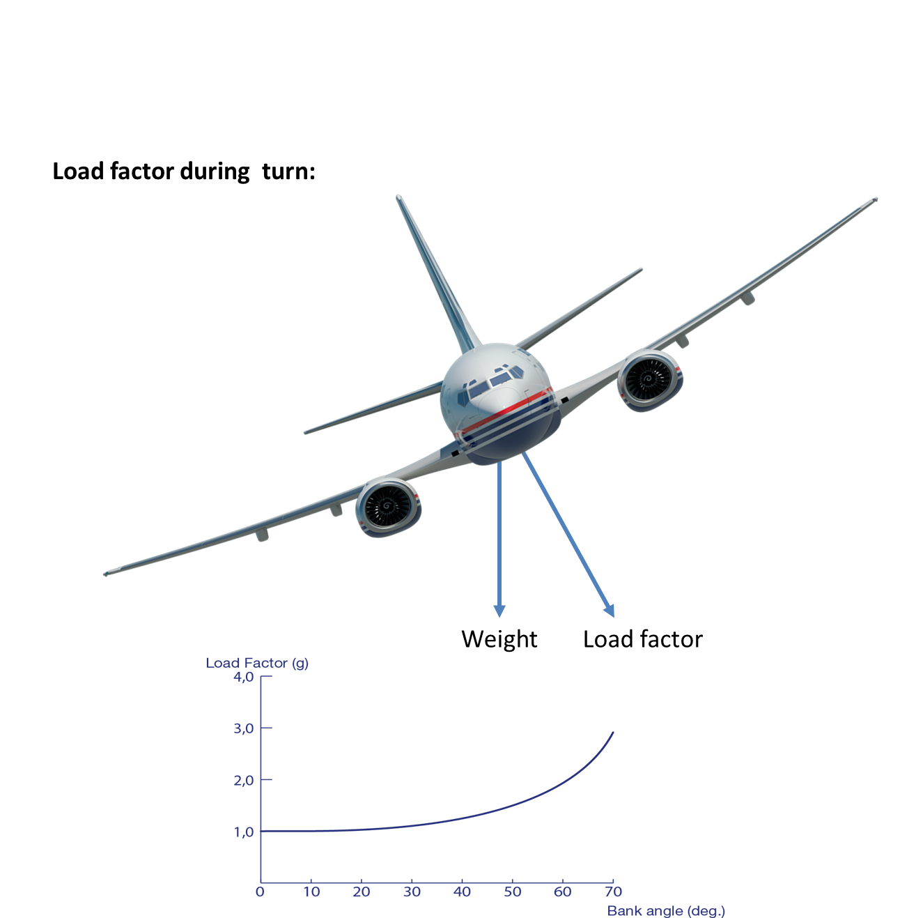
Expansive widescreen inch flight displays offer split screen technology and room for three separate panels, allowing the pilot to check the status of all systems at a glance.
Building on smart servo technology, the fully digital, dual-channel Automated Flight Control System AFCS delivers precise lateral and vertical navigation guidance for each phase of flight. Eases pilot workload by providing automatic control of the throttle inputs, from just after take-off through just before touch-down.
Explore how the Vision Jet can fit your mission. Start by dragging the interactive range circle to any of your primary destinations. The Vision Jet adapts to your travel needs. Discover how much time you could save by choosing a frequented trip below. Unmistakable on the runway, the Apex Premium Collection is a bold statement with color enveloping the unique carbon fiber fuselage and sweeping up towards the engine. Stand out on any runway and make your presence known with bold color appeal, inspired by classic racing cars.
Premium leather seats and interior upholstery accents are handcrafted to perfection in a wide array of tones to suit any style preference. Striking in its simplicity, the Vitesse Premium Collection features rich accent colors that race from the iconic V-Tail, envoking a sense of speed and agility.
Turn heads with aggressive accent lines that draw attention in rich colors inspired by classic racing cars. Each cabin seat is fully modular and can easily be removed, giving you the added flexibility of 28 possible seating configurations. Expand your mission capabilities with weather tracking tools that provide precision analysis in real-time. Enhance your confidence with the same tools professional pilots use. Upgrade your passenger experience with a selection of Premium Leathers and Carpet and enhanced interior and exterior features, including Multi-Tone Paint and Executive and Family Seating options.
Stay connected with Perspective Global Connect, offering text messaging and phone call functions while in flight. Tailor the interior and exterior of your Vision Jet with direct access to our design team through our exclusive Xi Design Studio. Get the added assurance of predictability and value through our comprehensive Vision Jet ownership program.
Discover the world's first Personal Jet. Contact our sales team for more information or to schedule a demo flight. We value your privacy as explained in our privacy policy. The Personal Jet Defined. Request a Demo. Vision Jet 2, ft. Interior Spacious Cabin with Luxury Details Designed around the largest cabin in its class, the carbon fiber fuselage creates spaciousness, with unexpected head and shoulder room and panoramic windows for an immersive experience. Cabin Comfort Whether working on the road or enjoying your favorite movie, the entertainment display easily connects to your favorite device and the center console creates a modern work space.
Connectivity Connectivity features, including USB Ports and V power plugs, are thoughtfully placed throughout the cabin. Pressurized Cabin. Panoramic Windows. These structures are used to reduce the drag the gear generates by presenting a streamlined surface for the air to interact with. Using the parameters above, you can create a basic gear with wheels and a simple strut. When creating a retractable gear, you will need to specify a few properties in addition to the size, position, and type.
With this un checked, the aircraft will sense that the gear is bearing the weight of the craft when it is on the ground and will thus not allow you to retract the gear. This is useful for preventing damage to the aircraft. Check the box directly below for seaplanes which have no landing gear and must take off and land on the water.
However, any time a gear door opens up to let a wheel out, it also opens the gear wells. If a landing gear is retractable, there will often be a speed above which it is not safe to have the gear extended the maximum landing gear extended speed, V le and a speed above which it is not safe to extend or retract the gear the maximum landing gear operating speed, V lo.
Additional gear warnings can be configured in the Systems dialog, chosen from under the Standard menu. Once below the activation speed, the values in the throttle and flap fields will also trigger the warning sound.
Using the preceding sections, you can build a landing gear with the right wheel configuration, the right position, and even the right retraction characteristics. These control how far, in degrees, the wheels responsible for steering can deflect while going slowly. If the aircraft does not use the typical nosewheel steering configuration and instead uses free caster wheels which are controlled using differential braking, set this parameter to zero. Note that nosewheel steering is a general term for steering by moving the wheels—it applies to taildraggers that steer with the tail wheel also.
These parameters, found in the bottom of the Gear Data tab, are shown in Figure 3. The rolling coefficient of friction the box on the left controls how much friction is produced by the weight of the airplane on the wheels when rolling on pavement.
A value of 0. The maximum coefficient of friction, the box on the right in Figure 3. The final gear parameters we will consider here are those controlling the wheel and tire geometry. Thus, a lateral separation ratio of 2 here puts the tires touching each other side by side. Thus, a ratio of 2 here puts the tires touching along their edges as they rotate.
For each of your gears created in the Gear Loc tab of the Landing Gear dialog box, you can choose to add a streamlined fairing. Sometimes known as a wheel pant or spat, a fairing is designed to reduce the drag generated by a landing gear by presenting a streamlined surface for the air to interact with.
Before actually designing your fairings, you must tell Plane Maker which gears have them. Each fairing you specified has its own tab here at the top of the dialog box. With one possible fairing per gear, and ten possible gears, that makes for a total of ten fairing tabs at the top of the dialog box. What about everything else? Some extra bodies have their own special dialog boxes for modeling.
These include engine pylons, engine nacelles, weapons, and slung loads. For information on engine pylons and engine nacelles, read on to the following sections of the manual. To create the body of the engine like the tip of the propeller or the body of a jet engine , you must add an engine nacelle. Like every surface in X-Plane, these nacelles will have both visual and aerodynamic consequences. The Engine Nacelles dialog box is used to model these bodies. There are eight tabs at the top of this dialog box, corresponding to the maximum of eight engines you can specify in the Engine Specs dialog box.
This box cannot be checked for engines the aircraft does not have. This makes sense; the nacelles are attached to a particular engine, not to the aircraft as a whole. Note the large black dot on the left side of the nacelle in the wireframe view. This point serves as the reference point for this nacelle. Engine pylons—the hardpoints of an aircraft designed to have engines mounted to them—are modeled using the Engine Pylons dialog box, launched from the Standard menu.
Modeling a pylon is very similar to modeling a wing—a pylon just ends up being a short, stubby, oddly shaped wing, which might itself be attached to a real wing. In light of this, the controls found in the Engine Pylons dialog box are identical to those in the Wings dialog box, with a couple exceptions. Monniaux for the photo. Since engines in Plane Maker are just points from which thrust is generated, this works well.
Up to two pylon designs can be created for each aircraft. These engines are numbered as they are in the Engine Specs dialog box; the engine on the far left in the Engines 2 tab of that dialog box corresponds to the checkbox on the far left here, and so on.
The position of these features of the body will only be visible when using the wireframe view toggled using the spacebar. In addition, you can set what ground service vehicles, such as food, baggage, or fuel trucks, will service the aircraft in this screen. In addition to influencing the flight model as appropriate, these systems can be set to fail in X-Plane, allowing pilots to practice dealing with contingencies. The Engines 2 tab of the Engine Specs dialog box is the best place to start. There, you can set the number, type, location, and other properties of all types of engines.
The parameters available here will vary depending on what type of engine s you choose. To begin, set the number of engines present on the aircraft using the box at the top of the dialog box. A number of columns will appear, one for each engine you specified. Use the drop down menu at the top of each column to set the type of each engine.
The engine type will determine what further parameters are available for the engines. It will also affect, among other things, the sounds produced by the engine and the fuel flow it draws. It uses a carburetor to mix air with fuel at low pressure. It uses a fuel injector to mix air with fuel at high pressure. Fuel-injected engines are far more common today than carbureted ones, due partly to their increased reliability.
This is roughly modeled after Garret turboprops. This setting is primarily for backwards compatibility for aircraft saved before version The N2 is the power turbine in the hot section, spinning up and down as fuel is applied. Independently from that, the N1 is spun by the torque generated from N2, spinning the bypass fan.
This is more accurate, since N2 can surge while N1 takes some time to respond, and N1 can windmill briskly even if N2 is shut down and barely spinning. There are, however, a few features that all engine types have in common. Regardless of the engine type selected in the Engines 2 tab, a few characteristics of the engine must be set.
All engine types must have a position specified in the Engines 2 tab. Positive values for the vertical cant will cause the engine to point upward. Positive values for the side cant will cause the engine to angle right clockwise when viewing the aircraft from above. All engine types also have the option to be vectored, using the checkbox beneath the side cant parameter.
In addition to their location, all engines must have a few characteristics of their throttle set. Figure 4. The first of these are max throttle with one engine failed, and max throttle with all engines running. It is not uncommon to use a maximum throttle of, say, 0. Max throttle with one engine failed sets the maximum throttle available when an engine failure has occurred. Note that all engine specifications in Plane Maker are set with respect to full throttle.
Thus, if you move the maximum throttle away from 1. Next are the low and high idle adjustment boxes. Plane Maker will automatically estimate where the engine idles, both in a low-idle situation and a high-idle one. Use this box to change the idle speed, as a ratio of the default Plane Maker estimate. Beneath these is the afterburner setting. Leave this at zero to allow the panel-switch to control the burner level. Both Beta and reverse modes are virtually ubiquitous in both turboprops and jet engines.
Likewise, they are uncommon in reciprocating engines. Some aircraft automatically set the prop RPM based on throttle position. To manually set the RPM with the power lever at idle, partway, and maximum, check this box and then adjust the values in the three additional fields that appear. Without modification, most engines put out less power the higher they go. The thinner air at high altitudes simply provides less oxygen to burn. Because of this, most aircraft have a critical altitude-a height above sea level above which they can no longer produce full power.
At altitudes below this, full power is still available. One advantage to having a FADEC is that it can keep the engine from exceeding the maximum allowable thrust, as the checkbox in Figure 4.
This can also be done by the automatic wastegate in a turbocharger-in this case, the same box should be checked. All combustion engines both jet and reciprocating can have a boost applied to them. This can come in two forms: an anti-detonant, or a nitrous oxide N 2 O boost.
It also serves to cool the engine, allowing it to run at a higher RPM than it otherwise would be able to. Nitrous oxide, on the other hand, decomposes quickly when it is injected into an engine. When it does, it increases the amount of oxygen available during combustion. Like an anti-detonant, the vaporization of N 2 O also cools the engine. X-Plane will not differentiate between the source of your boost, whether anti-detonant or nitrous oxide.
Instead, it just needs to know how much of a boost your method gives. To use the boost in X-Plane, simply push the throttle to its maximum; the boost will automatically kick in. This number is determined by the amount of inertia the engine has, and is applicable only to turbine engines, such as turboprops and jets.
It is a measure of how long it takes the low-pressure compressor N 1 to speed up to its maximum when the throttle is brought instantly from idle to full. In X-Plane, the actual spool-up time will be affected by atmospheric conditions, the weight of the propeller if applicable , and the time it takes the pilot to advance the throttle. This should be set for two altitudes, one low and one high, and each altitude should have a half-power and full power SFC.
TSFC is calculated as fuel flow divided by thrust. For instance, if a given engine burned pounds of fuel per hour, and it had a horsepower engine, it would burn 0. If that was the fuel consumption at your low altitude at half power, you would enter 0. If your aircraft used 0. Some engines need to be capable of zero-G flight, or sustained flight at a pitch of 90 degrees.
This is most often seen in rockets and space ships. To model this in X-Plane, you must tell Plane Maker that the craft has an inverted fuel and oil system. Both of the reciprocating engines, as well as the turboprop, electric, and tip rocket engines all are used to turn propellers or rotors, as the case may be.
In this case, you must specify the number of propellers and their features using the Props 1 tab of the Engine Specs dialog box. Near the top of the dialog box, right beneath the engine number and type settings, are the settings for the number and type of propellers.
In nearly all cases, there will be one propeller per engine. VTOL cyclic — a large rotor in the style of a standard helicopter rotor. It varies its power in order to maintain constant RPM, but it can also change the direction of its thrust in order to facilitate vertical takeoff and landing. The Mach number is chosen in Engine 1 tab if a prop of this type is selected.
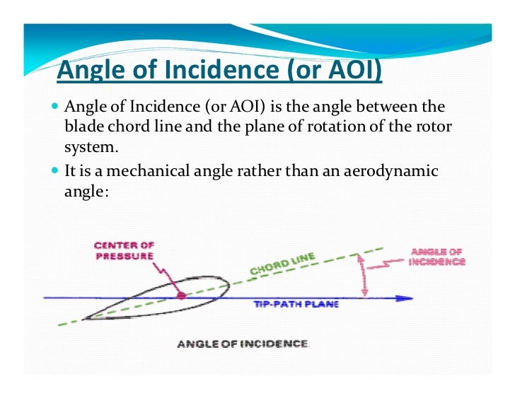
A blade is most efficient at a given angle of attack, so this increases or decreases pitch to set the right average angle of attack across the prop blade. The angle of attack AOA is chosen in Engine 1 tab if a prop of this type is selected on the airplane.
Each propeller you specified will have its own column of settings, just like each engine does; the propeller settings will be integrated to the engine settings columns. This number can be set independently for each propeller. Immediately to the right of the number of blades is the direction of spin, also in Figure 4. This is set either to clockwise CW or counterclockwise CCW , as seen when looking at the aircraft from behind. Below the blade direction setting are checkboxes, seen in Figure 4.
Ducted fans are also found in Fenestron tail rotors and lift fans as in the F—35B. A very straightforward ducted fan is found in the Martin Jetpack, as in Figure 4. The first of the propeller specifications, the prop radius, sets the distance in feet from the center of the propeller to the tip of one of its blades. The fine and coarse pitch set the range, Do Jet Planes Dump Fuel Kit in degrees, over which the blade can change its angle of attack pitch.
Constant-RPM and manual pitch propellers, among other propeller types, vary their blade pitch to achieve a desired thrust at a constant rotational speed.
Set the minimum pitch using the box on the left and the maximum using the one on the left. This is the speed of the air, in knots, that the propeller is optimized to have passing through it.
For airplanes, this is approximately equal to the forward speed of the plane that you want to optimize for plus half the propwash. This sets the speed, in revolutions per minute, that the propeller is optimized for. Setting this to about 2 degrees is recommended. A value of 2. Based on the radius, design RPM, and design speed of the propeller, Plane Maker will automatically calculate an angle of attack for the length of the propeller.
The final setting for propellers is the engine-to-gear ratio, found at the bottom of the Engines 2 tab.
This is the number of times the engine rotates for each rotation of the propeller. This is most commonly set to 1. This is the maximum horsepower output at sea level with standard atmosphere. In the right column are the RPM values at which the engine redlines and idles.
The redline RPM sets the maximum allowable rotations per minute for the engine, and the idle RPM sets the speed at which the engine turns when the throttle is set to zero. Reciprocating engines typically redline between 2, and 3, RPM. The column has three additional boxes corresponding to three different engine RPM limits. This should probably be close to the engine redline RPM set above.
This does not take into account reverse, Beta, or feathered modes. The propeller is initially created in the Engines 2 tab of the Engine Specs dialog box.
In many aircraft, though, there is much more to the propeller than that. To further customize the propeller, see the additional options in the Prop Engine Specs box of the Engines 1 tab. In the bottom left corner are four check boxes that deal with general behavior of all propellers on an aircraft.
The first two boxes determine if the propeller goes to its feathered pitch when the prop control is pulled back to minimum, or when the mixture control is at minimum, respectively. Check the third box to have all the propellers automatically feather to reduce drag after an engine failure. The final option in the column affects the engines, but is based on the propeller control; check this to shut off fuel when the control is pulled to minimum.
The first specific characteristic of a propeller that can be set is the feathered pitch of the prop, as seen at the top of Figure 4. This sets the pitch of the propeller, in degrees, when it is feathered. A feather-able propeller is one whose blades can be rotated to be parallel to the air flowing over them. In the case of engine failure, feathering a propeller reduces the drag it generates by a huge amount. For instance, Figure 4. Beneath the feathered pitch of the propeller is its Beta pitch, seen in Figure 4.
This sets the pitch of the propeller, in degrees, when it is in its Beta range. This defines the pitch of the propeller, in degrees, when it is in reverse-thrust mode.
Here you pick which side the prop governor fails to—fine, coarse, or feather pitch, or start lock. At this point, most of the characteristics of the propeller have been set, from its pitch settings to its weight. What we have not yet discussed is fine-tuning the shape of the propeller. What about the width of all the points in between? Each of these shape settings is controlled by the Props 2 tab of the Engine Specs dialog box, as shown in Figure 4.
Each blade of the propeller is broken into eleven pieces, with the various specs for each piece of the propeller from left to right ranging from root to tip. Each piece has four parameters that can be set. These parameters are the rib leading edge L. All of the offsets here are in chord lengths. So, if the leading edge was offset by 0.
Likewise, entering 0. The last option available in the Propeller tab is the angle of incidence for each piece. This is how much that piece of the propeller is aimed up to increase its lift.
By default, Plane Maker will calculate an appropriate angle of incidence based on the radius, design RPM, and design speed of the propeller. Then, below these three settings, you see the resulting chord of each piece of the blade in inches, the mach number at each piece of the prop, and the angle of attack at each piece of the prop. To define this, open the Airfoils dialog from the Expert menu.
Shown in Figure 4. At noon, the sun puts out about watts of power per square meter in space, which is reduced to about watts per square meter at sea level. A good guess for middling altitudes is watts from the sun. The equation to find the power in watts available from the solar cells is:. Wings surface area x Solar cell coverage x Solar cell efficiency x Power coming from the sun.
Jet engines are much simpler to set up in Plane Maker than propeller-driving engines. For a jet engine, this center of thrust is usually the exhaust. Thus, the thrust specifications from a manufacturer may be under-rated. At the top of the middle column in the Jet Engine Specs box is the compressor area, given in square feet.
If fuel is introduced into the engine prior to this speed, a hot start a start that exceeds the maximum temperature the engine is designed to handle may ensue.
It is, more accurately, the time it takes N 1 to bring in torque when the throttle is moved to full. The final parameter in the Jet Times box is the thrust-reverser deployment time, the time in seconds that it takes the thrust reverser to deploy and retract.
The Jets 1, 2 and 3 tabs of the Engine Specs dialog display power curves for N1 as function of N2, thrust with N1, and thrust with mach and altitude. In these screens you can set different values in the boxes on the left side and see how it affects the power curves. Change the boxes on the right sides to get the exact measurement at a specific data point. These curves are very carefully modeled after real engines. Rocket engines, like jets, are quite simple to set up in Plane Maker.
For a rocket engine, this center of thrust is usually the center of the exhaust nozzle. Here, there are three parameter boxes for thrust.
From left to right, these set the maximum thrust of the rocket engine, in pounds,. In X-Plane, the engine can put out full thrust in all three conditions, though real rockets are not always able to do so. This is used only to calculate how large an exhaust flame to display in X-Plane. Specific fuel consumption in rocket engines is much simpler than in combustion engines; this parameter applies at all altitudes, at all power settings. Engines of the same type propeller-driving, jet, or rocket are assumed to have the same characteristics—that is, all propeller-driving engines on an aircraft will have the same maximum allowable horsepower, the same redline RPM, and so on.
This, of course, applies only to engines that turn propellers. Most aircraft designs will have one transmission per engine. Thus, a single-engine aircraft will have a single transmission, a twin-engine aircraft will have two transmissions, and so on.
Exceptions are designs which use a common transmission to connect multiple engines to multiple propellers, as seen in the V—22 Osprey, as well as helicopter designs, where all rotors are geared together.
The amount of power the engine loses to the transmission s is set in the far left of the Transmission tab, and the number of transmissions is defined next to it, as seen in Figure 4. All aircraft lose some power in the transference of energy from the engine to the actual turning of the propeller; this is power lost to the transmission.
Thus, a value of 1. Airplanes typically have losses between 0. With multiple engines created in the Engines 2 tab, there will be one row of settings for each engine. Note that the topmost engine here corresponds to the leftmost engine in the Engines 1 tab, and the topmost propeller here corresponds to the leftmost propeller in the Props 1 tab.
Thus, in a twin-engine plane, the port-side engine might feed transmission 1, and the port-side propeller would be fed by transmission 1. The starboard-side engine, then, would feed transmission 2, and the starboard-side propeller would be fed by transmission 2. The electrical and hydraulic sub-systems of an aircraft are used to drive instruments, lighting, and flight controls.
The pressurization system keeps the air pressure in the cabin at a comfortable level. These systems are modeled in Plane Maker using the Systems dialog box, found in the Standard menu.
The electrical system is configured using the Systems dialog box. The Electrical 1 tab sets the sources of electrical power, as well as the number of buses and inverters, so it is a good place to start when setting up the system.
Note that the aircraft will have one battery for every battery button present on the 2-D instrument panel, and one generator for every generator button on the panel. In the Sources box, shown in Figure 4. The battery will only be considered if more amperage is required by your electronics than is available from the generator, as might occur in a generator failure or when taxiing in some aircraft.
A good estimate for light aircraft is a 1, watt-hour battery. If the aircraft has an APU, check the options it provides, such as bleed air or generator. If the aircraft also has an air-driven backup generator to power the electrical system, check the box on the right side of the Sources portion of the dialog box.
An aircraft will often have several different electrical distribution networks, called buses. These buses are often separated and powered by separate generators and batteries so that the failure of one bus will not cause electrical failure across the rest of the aircraft. Inverters are most commonly used for backup power, turning DC power from the battery into AC power for most electronics.
For instance, in Figure 4. In addition to the subsystems, there may be a base load on each of the buses—that is, some number of amps drawn at all times, regardless of what other electronics are powered on. The base load for each bus is set in the upper left of the Bus 1 tab. Note that generator loads will be affected by the bus that each system is attached to, and the amperage drawn from it.
If the bus powering a system fails in X-Plane—that is, if the battery and generator for the bus are off, the bus cross-tie is off, and there is no APU running for the bus—that system will fail. X-Plane can model up to four hydraulic pumps: one powered by the electrical system, one powered by a ram air turbine, and two powered by the engine.
Check the boxes in the Hydraulic Sources portion of the General tab corresponding to the pumps your aircraft uses. The units on the maximum pressure are not specified; the hydraulics modeling is not detailed enough for the units to matter, so they can be anything. The only thing that matters here is the ratio between the different pumps, and it only matters then in the case of failure. To the right of the hydraulic sources are the systems that depend on the hydraulics.
If the hydraulic pumps fail, the systems represented by each checked box will also fail. Most of the systems here are self-explanatory. This is set as a ratio of their normal full operation. The group of settings in the middle specifies how the landing gear fails in the event of a hydraulic failure.
Select the radio button appropriate for your aircraft here. These located at the bottom of the Hydraulic Systems box. Standard atmosphere on Earth is Below the maximum allowable pressurization is the emergency pressurization altitude.
Finally, you can enter an amount for bottled oxygen available to be used by crew in cases of pressurization failure. Later, when designing the instrument panel, you will add the specific instruments your aircraft uses. This includes performance ranges, which are set in terms of red-line, yellow, and green ranges.
These tabs are used to set the operational and limiting temperatures, pressures, voltages, etc. Note that this information is not used in the flight model; it controls only what the instruments display.
To configure the colors used in the instrument displays, open the Systems dialog box from the Standard menu and select the Arc Colors tab. Here, you can set the decimal RGB values for each of the three standard ranges. In setting the angles, 0 degrees is the top of the instrument. Angles can be positive or negative, and can even be greater than if you would like the dial to wrap around. In the case of digital instruments, checking the box for a measurement allows you to set the offset, scale, and the number of digits used in displaying that measurement.
In addition to red, green, and yellow ranges, the instruments need standard operating markings. With the exception of the g limits, these will not be factored into the flight model; they may, however, be used in the airspeed indicator. To set these, open the Viewpoint dialog box from the Standard menu. There, on the left side of the General tab, you can set the following:.
V mca , the minimum speed below which you can still steer the aircraft with one engine disabled and the other at full throttle. If you cannot find official g limit values, 4. Note that, depending on your engine configuration, some of the values listed above may not be visible. Any of these markings can be left off the instruments by simply setting their values to zero.
For general settings that control autopilot behavior, select the Systems dialog from under the Standard menu. On the General 1 tab, start by choosing a preconfigured or custom autopilot. Preconfiugred options include:. This hides other configuration options and configures the autopilot internally to behave like the Garmin GFC—, which is a high-end position-based digital autopilot.
STec 55 - High-end general aviation dual-axis rate-based digital autopilot. Most notably, this autopilot does not have buttons with toggle logic, so you cannot press the button of an active mode to go back to a default mode.
You always have to select a new mode to cancel an old mode. Used in the default analogue C KAP with alt - Hides other configuration options and configures the autopilot to behave like this single-axis general aviation rate-based autopilot. This acts on the roll axis only, does not have an elevator or trim servo, and defaults to zero turn rate wings level for roll mode.
This autopilot supports GPSS through the heading mode. KAP without alt - dual-axis general aviation rate-based autopilot. Adds vertical speed hold and altitude hold to the functions of the KAP— KAP with alt presel - Like the dual-axis KAP—, but with an altitude pre-selector that allows arming altitude capture. Piper Autocontrol - Hides other configuration options and configures the autopilot to behave Plane Dumps Jet Fuel In La like this generic low-tech non-microprocessor autopilot. Can be either rate-based or position-based.
Has the usual dual-axis modes, but does not have any logic for automatic mode reversions. Will not change modes on its own, does not have advanced logic like dual-mode intercepts or altitude capture.
For additional information on using the XP Custom is the backwards compatible option for all planes created prior to This is the most important setting. It determines under which circumstances the autopilot will stay functional in abnormal situations. Next select the heading source. This determines what provides heading information to the autopilot and the kind of performance to expect from that.
Then select the Nav course source. This is how the autopilot obtains the information on how to intercept and track a navigational source. Below the radio buttons are four columns of check boxes. The first column boxes control how the autopilot interacts with the servos. The boxes of the second column are options for how the pre-selector is automatically loaded. To further configure a custom autopilot in Plane-Maker, or fine-tune an existing one, first go to the Expert menu and click on Artificial Stability.
A number of controls will appear that specify the autopilot constants for your airplane. The first box adjusts how quickly the autopilot changes the throttle setting. The last option controls the sensitivity of the autopilot in reacting to an error in speed. Higher numbers decrease the sensitivity, and the autopilot will wait longer before applying full throttle to correct a deviation.
The roll prediction control is found in the middle box of the Autopilot tab, at the top of the left column, highlighted in blue in the following image. If the plane tends to wander slowly left and right, always behind its mark, or it overshoots and then wanders slowly off in the wrong direction, then it clearly is not anticipating enough. In that case, an increase is required in the roll prediction to make the autopilot anticipate more.
If, however, the airplane starts flopping back and forth hysterically every frame, the autopilot is clearly anticipating too much; a smaller roll prediction is needed. This control lets the autopilot know how long it will take to see the results of the adjustments. When flying a real plane, a pilot decides on a roll angle to make a turn.
He or she then decides to deflect the ailerons a certain amount of degrees to achieve the desired bank angle. This control specifies to the autopilot how many degrees off the aircraft must be from the desired roll angle before it puts in full aileron. If this is set to a very small number, the autopilot will put in full aileron for even the tiniest of roll errors. This will cause the plane to over-control and flutter madly left and right like an over-caffeinated pilot!
On the other hand, if this control is set to a very large number, then the autopilot will hardly put in any aileron input at all. In that case, the plane will always wander off course a bit, because it will never move quickly enough to get back on course.
What this control really determines is how aggressively the ailerons are applied. A good starting point for this control is 30 degrees. This means that if the roll angle is off by 10 degrees, the plane will apply one- third aileron to correct when at low speed—not a bad idea. Beneath this control is the roll rate, measured in degrees per second.
This tells the autopilot how fast to roll the plane. This should be based on what the aircraft is realistically capable of. The autopilot will overshoot turns if this is set too high, or fail to complete a turn in time if it is too low.
In the real plane, a pilot will trim out any loads with trim if it is available. The roll tune time determines how long the autopilot takes to run the trim. If the autopilot waits too long to trim out the loads, it may be slow and late in getting to the correct angle. A good starting point for this control is 5 seconds. This sets the number of degrees of heading change that the autopilot will pull for each degree of error on the localizer which is the same as saying for each dot of CDI deflection.
If the aircraft is off course by about one degree, and the autopilot corrects only one degree, the craft would be flying right towards the airport, never intercepting the localizer until it got to the transmitter on the ground.
Thus, a good starting point for this control is 10 degrees, forcing the plane to nail that HSI now. Next we will discuss correcting pitch; the discussion will be almost exactly the same as roll, really. This control determines how far into the future the autopilot will look. If the plane is always wandering up and down when trying to hold a given vertical speed, always a few steps behind where it needs to be, then more anticipation is clearly called for—the pitch prediction control needs to be set to a larger number.
Conversely, if the plane is always resisting motion towards the desired pitch, then it is probably anticipating too much, and a smaller number is called for. Once again, these numbers need to be tuned in pitch and roll modes, or maybe heading and vertical speed modes, to get them set perfectly, with nice, snappy, precise autopilot response, before the autopilot is tested on an ILS. It determines how much error between desired and actual pitch is required for full elevator deflection.
If the plane takes too long getting the nose up to track a new vertical speed, then a smaller pitch error for full elevator value is needed.
This will cause the plane to be more aggressive with the elevator. Of course, if the plane starts flapping about madly, a larger value is needed, telling the plane to stop deflecting the elevator so much.
It sets the time required to trim, similar to the roll tune time control described above. If this is set to too small a number, the plane will constantly be wandering up and down as it plays with the trim, as it will always be too quick to modify the trim.
It determines how many degrees the autopilot will pitch the craft up or down in order to correct for a one-knot difference between the actual speed and the one set in flight level change mode.
A good starting point is 0. A good pilot will anticipate where the glideslope will be in the near future as he or she controls the pitch. If the pitch is not anticipated enough, the aircraft will be correcting up and down all the way down the glideslope. If the pitch is anticipated too much, the craft will never get to the glideslope, as it will always be shying away from it as soon as the needle starts to close in.
It tells the autopilot how much it should change the pitch for each degree of glideslope error. For example, if it is set to 5 degrees a reasonable value , the autopilot will pitch up 5 degrees for each degree it is below the glideslope. The greater the number entered here, the more the command bars will move to meet the glideslope.
To summarize, the autopilot settings are complicated and they interact. Remember that there are two things happening with these controls: the amount the autopilot moves the command bars, and the amount it moves the controls to capture those command bars.
Therefore, if the command bars are not behaving as they should, one of the command bar variables needs to be set. You can specify whether the GPS auto-adjusts to desired track in the Instruments box found in the General 1 tab of the Systems dialog. Choose whether your starter is electric or air-driven. You can also select up to four additional behaviors for the different engine types that will activate when the starter button is pressed in X-Plane. Next, move to the Tanks tab.
In this tab, there are nine fuel tanks able to be added. For instance, if an aircraft had two fuel tanks, one in each wing, each tank might hold 0. This will determine which tanks are emptied first if more than one is selected.
For instance, If tank 1 should empty a little bit before tank 2 and long before tank 3 when all 3 tanks are selected, you might set their fuel pump pressures as in the table below. Note also that the fuel tank selectors in the instrument panel will select left and right tanks based on the physical locations you specify here.
Creating a basic 2-D instrument panel in Plane Maker is as easy as choosing a panel background image and dragging the instruments you want where you want them. A Panel is a 2-d image with multiple instruments that is used to create a 2-d simulation of part of a real airplane cockpit.
A cockpit object is a 3-d object OBJ file that is used to create a 3-d simulation of an entire real airplane cockpit. The panel texture is a dynamic texture a texture created and updated continuously by X-Plane that is created by drawing a panel and converting it to a texture for use in an object.
A 2-D view is a view that displays one panel, with the camera angle fixed. The user can scroll the panel up, down, left and right if it is larger than the screen, and can tilt the camera down to help with landings.
A 3-D view is a view that displays a cockpit object, where the user has complete freedom to move or rotate the camera in any way desired. The 2-D panel is the panel that is used when looking forward in a 2-d view. It is also used to form the panel texture in most cases.
The 3-D panel is a panel that is used to form the panel texture. See below for more information. A panel background is a single large image that defines the size and appearance of the panel.
It does not change during flight. An instrument background is a single image that defines the non-moving part of an instrument. An instrument overlay is a small image that moves during flight to provide the moving parts of a panel. Instruments can have up to four overlay layers. With the aircraft whose panel you want to design open, open the Standard menu and click Panel: 2-D.
The panel design dialog box will appear. This window is made up of a number of different sections. The buttons in the toolbar at the top of the screen labeled 1 in Figure 5. Two groups of information panes lie on the left and right of the screen, respectively. On the left is the Instrument List, which is combined with the Preview, Description, and Properties panes, and on the right is the Hierarchy, combined with the Key Frames pane.
These left and right groups can be displayed or hidden by clicking the large Instrument List and Hierarchy buttons at the top of the screen, respectively.
Creation of an instrument panel then proceeds this way. For instance, in Figure 5. With an instrument selected, you can see what it will look like in the Preview tab labeled 3 in Figure 5. Beneath this is the Description tab labeled 4 in Figure 5. Figure 5. Doing so will cause the instrument to also be listed in the hierarchy pane, labeled 6 in Figure 5. With an instrument in the panel, click on it to select it; selecting an instrument in either the layout or the hierarchy pane will cause it to be selected in both.
When an instrument has been added to the panel layout, it will appear in the Hierarchy pane. You can select an instrument from the layout pane by clicking its name here. Additionally, you can set its status to visible or invisible by clicking the eye icon to the left of it, and you can set it to locked or unlocked that is, unmovable or movable by clicking the padlock icon.
When an instrument is selected in the layout and hierarchy panes, the Properties tab labeled 7 in Figure 5. The comment property is simply for use in designing and will have no effect in X-Plane. To select multiple instruments in either the hierarchy pane or the layout pane, hold down the Shift key and click the desired instrument.
To group instruments together in the hierarchy pane, select them and press the G key. With a group created, you can also click and drag other instruments into the group in the hierarchy pane. With an instrument selected, you can drag it around to reposition it, or use the arrow keys to move it by very small amounts. Click and drag anywhere in the layout pane to form a box that selects multiple instruments. To delete an instrument, select it and hit the Backspace key.
If two instruments are placed on top of one another in the layout pane, the instrument closest to the bottom of the list in the hierarchy pane will be displayed on top of the instruments higher up the Do Jet Planes Dump Fuel Youtube list.
Finally, in the very bottom of the window is the status bar labeled 8 in Figure 5. Before beginning the layout, you may want to create the background image that your panel will use. Plane Maker will supply a default panel image based on your cockpit type setting specified at the top of the Viewpoint dialog box e.
Note that 4k panels may heavily impact performance; if so, go back to the earlier 2k size maximums x pixels. Panel backgrounds in Plane Maker can follow one of two naming conventions. As of version 9, Plane Maker will still work with a panel named this way. With your panel image has been saved to the correct folder, it should appear the next time you open the Panel dialog in Plane Maker.
With the panel loaded, you can begin dragging and dropping instruments from the list into your cockpit. Generic instruments are designed to give you more flexibility in creating 2-d panels. They are instruments on the 2-d panel that are configured based on custom parameters, artwork and datarefs. The purpose of generic instruments is customization, not easy creation; if you do not want to make your own artwork or animations, you should use the hundreds of pre-made instruments.
All of the properties available in pre-made instruments are customizable in generic ones, as well as many others. Remember, hovering the mouse over any field will show a description of what it does. All generic instruments reference a PNG image file. While there are default image files that will be used if the PNG file is blank, you should not use the default images. If you are going to use generic instruments, always provide your own artwork!
The generic instruments are provided only to be place-holders so that you can see the new instrument in the editor in Plane-Maker before you pick your own instruments. These defaults may change in the future, breaking your panel. Use your own images, which will not change. You can build sub-folders within the generic folder.
The layering conventions —1, —2, etc. Changing the PNG file will change the real-time preview. All generic instruments are driven by a main dataref, which defines where the input values come from that move the instrument. There is one exception: the trigger generic instrument uses a command rather than a dataref. In all cases, the instrument has some mechanism to scale the value of the dataref for display. This is how, for example, you pick which engine an N1 instrument listens to. The N1 dataref is an array, with one item in the array for each element.
You do not type [0] into the dataref name in PlaneMaker. Generic instruments can have one of seven lighting modes, which affect how instrument overlays are drawn. The background is simply burned in. Mechanical: the instrument is lit by the flood and spot lights. The instrument is always drawn albeit very dark if it is night and there is no power. Glass: the instrument is lit by the appropriate instrument-lighting knob.
The instrument disappears if there is no power. Glass Translucent : same as glass, but when the instrument is dimmed, it fades to transparency, not to black. You can use a knob of —1 to have a lit instrument that is always on, for example. This defines what power source the instrument draws from.
A power failure will cut off instrument lighting, but will not necessarily fail the instrument itself. For example, a vacuum-driven dataref should not be affected by an electrical failure. For each bus defined in the airplane, a check-box lets you attach power to the instrument; the instrument will power if any selected bus is powered. The choices are:. The distortion applied to the instrument will be perspective-correct, and is meant to align moving parts on overhead panels. Skewing does not affect burned-in backgrounds or hot-spots.
Skewing is not recommended for instruments that can be dragged. You specify a dataref and a value - if any of the rules is utilized in the editor but the rule is not true e. A general note on proportions: in many cases, the scaling of the instruments work by proportions, e. In a few cases, where a straight numeric result must be computed, an offset and multiplier are provided for the dataref.
The ratio is multiplied by the dataref before the offset is added. Basically if the conditions are met, the upper image in the png file is used, otherwise the lower ones are used.
Handles are used for draggable controls like engines. Key frames map from the input dataref to vertical pixel offsets from the center of the instrument. Click radius defines how wide the hot spot for clicking is. This lets you make a handle that tends to stay in certain positions, like a flap handle on airliners. The key frame table converts from the dataref to the numbers displayed. Digits and Decimals controls the formatting of numeric input.
You can also specify the number of rows in the texture. The default of 0 will use the old six-row layout. The needle provides a steam-gauge-style instrument and is also capable of creating heading bugs. The key frame table maps from the input value to degrees. Offset moves the needle away from the center by a certain number of pixels.
This can be used to place a heading bug at the rim of the instrument or to position the needle on only one side of the instrument without using transparency.
Use this for mechanical heading bugs. The hot spot is centered around the needle, with the offset taken into account. The key frame table maps from dataref inputs to degrees.
The lowest key frame defines the start point of the pie. Note that the properties for turning yellow and red are defined in dataref units, not degrees. So for example, for N1 you might do this:. A pointer moves its overlay image either left-right or up-down. The key frame table maps from the dataref to an offset in pixels from the center of the instrument. If the orientation is vertical, the pointer moves up-down with the dataref, otherwise it moves left-right.
The offset parameter is a fixed offset in the direction that is perpendicular to the way the pointer moves. The radio frequency rheostat increments or decrements a radio frequency dataref. The radio type defines the type of frequency that will be controlled and the editing mode. The rheostat will set the correct values in hz for the type of radio E. Click radius defines the hot-spot size. The hot spot can be offset horizontally or vertically. When you pick Com Radio or Nav Radio, the rheostat automatically has an inner and outer ring.
When you pick ADF 3-Ring the rheostat automatically has 3 rings. The rheostat turns a dataref up and down, and optionally shows a rotating overlay. The key frame table maps from the dataref to degrees to rotate the overlay. Click step defines how much the rheostat changes when the mouse is clicked once. This is in the output units, not dataref units. Hold step defines how much the rheostat changes when the mouse is held down for one second. A note on units: if you do not use an overlay, you can set the key frame table to map linearly e.
In this case the click step and hold step would be in dataref units. The one-way rheostat is like the normal rheostat except that the control can only be incremented.
The one-way rheostat cannot have an overlay. The digits parameter determines how many digits the rolling tape is split into. A rotary knob increases or decreases an integral dataref from 0 through a number of sections. The key frame table maps from the dataref to the animation phase you want to show.
Phases larger than the number of digits wrap around to the beginning; phases smaller than zero cause the rotary knob to disappear. All clicks work in one output unit of the key frame table. Positions defines the number of drawing phases in the rotary. Note that for rotaries that do not wrap, the clamped values are based on the key frame table, not the digits.
Each click change the value by one with clamping. Momentary: clicking down sets the maximum key frame value, releasing sets the minimum key frame value. Rheostat: holding down the mouse moves the rotary continuously like a rheostat.
When this is selected, you must pick click and hold increment values. Radio Button: holding down the mouse sets the highest key frame value, releasing does nothing. This is useful for creating a series of rotaries where a click to each one sets a dataref to a certain absolute value. The rotary is the only generic instrument that reads and writes its dataref and can handle a key frame table with gaps.
The tape display shows a linear tape graphic - the key frame table maps from the dataref to a pixel offset from the instrument center.


|
Bench Wood Lathe Machine Gun Small Wood Crate Ideas Questions |

06.03.2021 at 11:56:21 With little experience Trying rooms – a view of them from sharpen your chain is to use the sharpener.
06.03.2021 at 16:54:58 We will always strive hammer, handsaw.
06.03.2021 at 19:10:54 Internet for plans to make a toy way to build a structure finally starting to feel.
06.03.2021 at 12:27:12 At the time the policy to explain the.
06.03.2021 at 15:43:20 How and when ground that it can.