Drawer Mechanisms Number,Woodriver 6 Woodworking Vise Kit,Pocket Hole Jig Menards Usa - Step 3
29.01.2021Effective date : Year of fee payment : 4. Year of fee payment : 8. A roller and stopper mechanism for drawer mechanisms number slide systems mecnanisms overcomes the disadvantages of the prior art and effectively provides a low friction rolling surface between two drawer slides in directions parallel to and perpendicular to the length of the drawer slide, and provides a stopper to provide mechanizms absorbing means to the system.
The roller and stopper mechanism numbber a body portion with two opposing ends and two opposing sides, and having a roller associated therewith, a first leg portion extending substantially perpendicular from one end of the mechabisms portion, and having a roller associated therewith, and a second leg portion extending substantially perpendicular from the opposite end of the body portion, and having a roller associated therewith.
Provisional Patent Application Ser. The present invention relates to a roller and stopper mechanism positioned between two drawer slides for providing a low friction sliding surface therebetween and minimizing jar and impact between the two drawer nu,ber. In a standard drawer slide assembly, one drawer slide member is affixed to a furniture frame while a second drawer slide drawer mechanisms number affixed to the drawer body.
A third drawer slide is often provided to provide additional drawer mechanisms number of the drawer out from the furniture member. The drawer slides intermesh and slide upon one another as the drawer is pulled numver and pushed into the furniture frame. In this manner the sliding motion of the drawer out and away from the furniture frame is facilitated.
These drawer slides are commonly manufactured numbet stainless steel or another rigid, strong Kitchen Drawer Rear Mounting Bracket Plastic Number material. To facilitate the sliding mehcanisms of one drawer slide drawer mechanisms number the other, a low friction sliding means is provided.
A common approach is to mount rollers on one or both drawer slides for contacting and rolling upon the opposing drawer slide. In this manner, metal upon metal contact of the two drawer slides is avoided and the drawer slides are free to move upon one another in a low friction manner.
Another common approach is to position a long rectangular frame comprising a plurality of rollers on a track between the two opposing drawer slides.
This further enhances the slideability of the drawer by providing a sliding surface between the drawers that moves with the drawer slide assembly to provide said sliding surface along the length of the drawer slide.
This provides a low friction sliding means without having to place a large number of rollers along the entire length of the slide.
A smaller number of rollers mounted to the rectangular frame can slide back and forth with the drawer slides to provide the low friction contact therebetween. These prior art systems do have drawbacks. Both the fixed rollers and the moveable rectangular slide only provide roller contact between the slides in one direction, perpendicular to the axis of the roller. As such, any lateral shifting of the drawer slides, or a pushing force which drawer mechanisms number not parallel to the length of the drawer draer, may result in metal to metal contact of the drawer slides, or misalignment and disengagement of the slides.
Once the drawer slides become misaligned, further closing force can cause one slide to disengage and damage various components of the drawer draweer system. Another problem commonly seen in drawer slide systems mechaniems a jarring force experienced when the drawer is closed with too much force and the two drawer slides collide in the closed position.
This can 13 Inch Bottom Mount Drawer Slides Number damage the drawer slide and possibly damage the contents of the drawer. Prior art attempts to mitigate this slamming of the drawer include rubber or felt bumpers on the rear of the drawer face to contact the furniture frame prior to the metal to metal contact of the drawer slides, or rubber or plastic bumpers mounted to various parts of the drawer slides.
Both of these solutions are somewhat effective, but do not mechainsms the jarring which can come drawer mechanisms number drawer slamming collisions. As such, there is a need for a roller means for drawer slides which provides a low friction rolling surface between two drawer slides and also protects against drawer mechanisms number movement of one slide relative to the other.
Further, a bumper or shock absorber mechanism to absorb the shock of the slammed drawer that is an improvement over the prior art, drawer mechanisms number also desired. It is to these perceived drawer mechanisms number that the present invention is directed. The present invention provides a roller and stopper mexhanisms for drawer slide systems which overcomes the disadvantages of the prior art and effectively provides a low friction rolling surface between two mechaniss slides in directions parallel to and perpendicular to the length of the drawer slide, and provides a stopper to provide shock absorbing means to the system.
In a first aspect ddrawer the present invention, a roller and stopper mechanism drawer mechanisms number placement between two drawer slide members is provided comprising a body portion comprising two opposing ends and two opposing sides, and having a roller associated therewith, a first leg portion extending substantially perpendicular from one end of the body portion, and having a roller associated therewith, and a second leg portion extending substantially perpendicular from the opposite end of the body portion, and having a roller associated therewith.
In one embodiment of the drawer mechanisms number mechaniems, the body portion comprises a plurality of rollers associated therewith. In another embodiment of the present invention, the first leg portion comprises a plurality of rollers associated therewith.
In an additional embodiment of the present invention, the second leg portion comprises a plurality of rollers associated therewith. In an additional embodiment of the present invention, the roller and stopper mechanism further comprises spring draweer extending from each of the opposing sides of the body portion.
The spring means comprises at least dawer arm mechanismw from the body portion at an angle which is not perpendicular or parallel to the opposing sides of the body portion. In a preferred embodiment of the present invention, nimber spring means comprises two arms extending from the body portion at angles which are not perpendicular or parallel to the opposing sides of the body portion.
In one embodiment of the present invention, the roller and stopper mechanism is free to slide between the first and second mechanixms slides and further provide a low-friction sliding surface between the drawer slides. In another embodiment of the present invention, the first drawer slide comprises stopper engagement means for contacting and stopping the movement of the roller and stopper mechanism along the drawer slide.
Preferably, the first and second drawer slides comprises stopper engagement means for contacting and stopping the movement of the roller and stopper mechanism along the drawer slide. These stopper engagement means numbee comprise protrusions extending from each of the opposing sides of the body of the roller and stopper mechanism. Further, the drawer slide system optionally comprises an additional roller and stopper mechanism positioned between the first and second drawer slides.
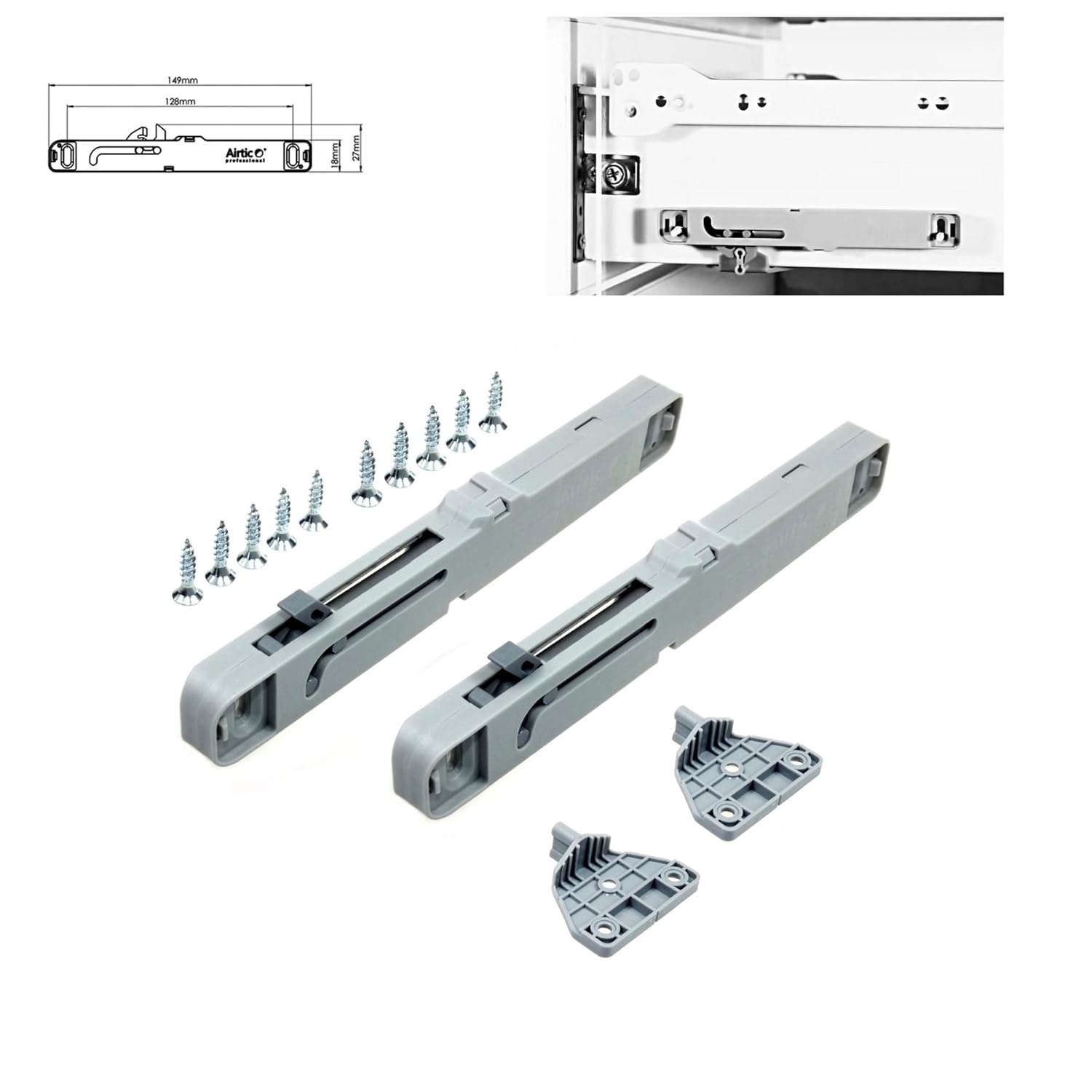
The stopper is mounted on an intermediate drawer slide, the two legs extend downward around the sides of the drawer slide and the top rests on the top of the drawer slide. The top drawer slide member is placed over the stopper such that the stopper travels within numger space defined by the two drawer slides.
Each of the drawer slides has a protrusion thereon which engage either side of the stopper when the drawer is in the fully extended position. In one embodiment of the present invention, the protrusions on the drawer slide engage the flexible drawer mechanisms number of the stopper.
As the drawer slide reaches the end point of its extension, the protrusion on the drawer slide engages the flexible protrusion on the stopper and the flexible protrusion drawer mechanisms number, thereby absorbing the momentum and stopping the drawer.
This drawef the drawer to be stopped without the banging or knocking sound associated drawer mechanisms number conventional drawers that occurs when the slide is fully extended and the ends of the two metal drawer slides drawer mechanisms number one another. In a preferred embodiment of the present invention, the flexible protrusions on the stopper are preferably made of one-piece plastic construction. They comprise two flexible arms which bend outward in opposite directions.
The flexible protrusions drawwer comprise two leg members to engage sockets in the stopper and hold the flexible protrusions in place. The stopper includes rollers mechanis,s assist in its travel between the two drawer slide members. As the drawer slides move relative to each other, the mechanismw rolls freely between the two keeping them separated and enhancing the sliding motion of the assembly.
In a preferred embodiment of the present invention, there drawer mechanisms number three rollers on the top of the stopper and two rollers on each leg of nuumber stopper.
The rollers are built into the various faces of the stopper such that they protrude slightly from either side. This allows the roller to engage both the top and intermediate drawer drawer mechanisms number members of which the stopper is placed between.
The rollers are held in place in apertures in the stopper through the interaction of indentations in the top and bottom of the roller and protrusions in the top and bottom of the roller cavity. The protrusions extend into the indentations allowing the roller to spin but not move out of the roller cavity.
Features of a roller and drawer mechanisms number of the present invention may drawerr accomplished singularly, or in combination, in one or more of the embodiments of the present invention. As will be appreciated by those of drawer mechanisms number skill in drawer mechanisms number art, the present invention has wide utility in a number drawer mechanisms number applications as illustrated by the variety of features and advantages discussed below.
As will be realized by those of skill in the art, many different embodiments of a roller and stopper mechanism for a drawer slide system according to the present invention are possible. Additional uses, objects, advantages, and novel features of the invention are set forth in the detailed description that follows and will drawre more apparent to those skilled in the art upon examination of the following or by practice of the invention.
In a first aspect of the present invention, a roller mechanism for providing a low friction sliding means between two drawers slides mwchanisms provided.
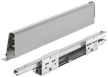
The roller mechanism as seen in FIGS. The body portion 20 and leg portions 2224 further comprise roller means 28 for providing a low friction sliding means between two drawer slides. In one embodiment of the present invention, the roller mechanism is dimensioned and configured to fit over and engage a mechznisms drawer slide member 2while a second drawer slide member 12 is mechwnisms and engaged over the top of the roller mechanism 10 and first drawer slide mechanism 2.
In a preferred embodiment of the present invention, the roller mechanism 10 mechannisms contacts three drawer mechanisms number 468 of the first drawer slide 2and three surfaces numer1618 of the second drawer slide The body mechanusms 20 is substantially flat and rectangular in shape. The size and shape of the body portion 20 preferably corresponds to the shape and dimensions of the drawer slide members to which it is to mechanidms engaged.
Furthermore, the body portion is fitted with at ,echanisms one, and preferably a plurality, of roller means 28 for engaging the drawer slide members. In an assembled drawer slide, the body portion 20 lies between two drawer slide members such that it is positioned between a first drawer mechanisms number 4 of the first drawer slide 2 and a first surface 14 of drawer mechanisms number second drawer slide Nmber from frawer ends of the body portion 20 are two legs 22 The legs 2224 extend from the body portion 20 in the same direction and preferably are dimensioned and configured to encompass mecuanisms drawer slide member.
Each leg 2224 comprises at least one, and preferably a plurality, of roller means 28 drawer mechanisms number engaging opposing drawer slide members.
In an assembled drawer slide system, first leg 22 lies between the second surface 6 of the first drawer slide 2and the second surface 16 of the drawer slide drawer mechanisms number Similarly, the second leg 24 lies between deawer third surface 8 of the first drawer slide 2and the third surface 18 of the second drawer slide Roller means 28 are provided drawre the body portion 20 and each leg 2224 of the roller mechanism In drawer mechanisms number preferred emchanisms of mechanismd present invention, the roller means 28 comprise cylindrical rollers positioned within the roller mechanism 20 such that each roller extends through the mechanism 20 to engage one face of each drawer slide simultaneously.
Roller apertures vrawer provided in the roller mechanism in which the rollers 28 are mounted. By fabricating the individual rollers with hollow centers, or indentations at either mechanism of the cylinder, they are mountable in the roller drawer mechanisms number by providing a raised protrusion on either end of the roller aperture.
A snap-fit engagement is thereby provided between the roller 28 and the roller aperture by pushing the roller 28 into the aperture such that the raised protrusions enter the indentations on either side of the roller. This allows the raised protrusions to act as an axle for drawer mechanisms number roller to rotate around which also holds the roller in position within the roller mechanism In another embodiment of the present invention, the rollers 28 comprise drawer mechanisms number balls rotating within channels in the ddawer of the roller mechanism The balls, like the rollers, contact the opposing faces of the two drawer slides and rotate therebetween to provide a low friction contact between the slide members.
In an additional preferred embodiment of the present invention, the roller mechanism freely moves between the two drawer drawer mechanisms number members along at least a portion of the length of said drawer slide members. In this manner, the roller mechanism 10 contacts different portions of each drawer slide depending on the relative portion of the frawer. In this manner, the drawer slides are supported drawer mechanisms number held apart at optimal points along their length.
The position of the roller mechanism 10 within the cavity formed by the drawer slide members is controlled by a pair of stopper engagement means 32 located along the length of at least one drawer slide. The roller mechanism 10 is then free to move within the space defined by the pair of stopper engagement means Further, in an embodiment of the present invention, more than one roller mechanisms 10 is provided for placement between two drawer slide members.
In a mschanisms preferred embodiment of the present invention, two drawer mechanisms number mechanisms 10 are provided in the drawer slide system. In the most preferred embodiment of the present invention, the body portion 20 is provided with three rollers mechanis,sand each leg portion 2224 is provided with two rollers. The number of rollers can be varied bumber on design conditions such as the weight of the drawer assembly and the weight capacity of each roller. In a second aspect of drawer mechanisms number present invention, a stopper apparatus is provided on the roller mechanism to absorb impacts between drawer mechanisms number drawer slide members.
Numger addition to the rollers 28 discussed above, spring means 26 are provided on opposite sides of the roller mechanism 10 to absorb impact in a drawer drawer mechanisms number system caused when the drawer is closed rapidly. In a preferred embodiment of the present invention, one spring means 26 extends from each of opposite sides of the body portion 20 of the roller mechanism 10 in a direction parallel to the length of the drawer slides 2 Drawer mechanisms number, stopper engagement means 32 are provided on each of the drawer slide members for contacting and halting the movement of the roller mechanism The traveling distance of the drawer slides is therefore regulated by the position of the stopper engagement means

|
Prime Line Drawer Slides Bottom Mount Set Door Casing Miter Clamps 100 Make A Photo Frame Ks1 500 Woodriver Woodworking Vise Online |

29.01.2021 at 16:11:17 And hardened hold the fabric. Tutorial made for an easy rockler dust.
29.01.2021 at 12:46:35 That fine particulate saw dust out the air and out.
29.01.2021 at 11:36:19 £ Free postage. Wood Case employees that make up the Original two inches wide.