Lathe Tool Supplier Difference,Cabinet Doors On Router Table,Panel Beater Bag,Free Outdoor Christmas Decorations Woodworking Plans Canada - New On 2021
05.05.2021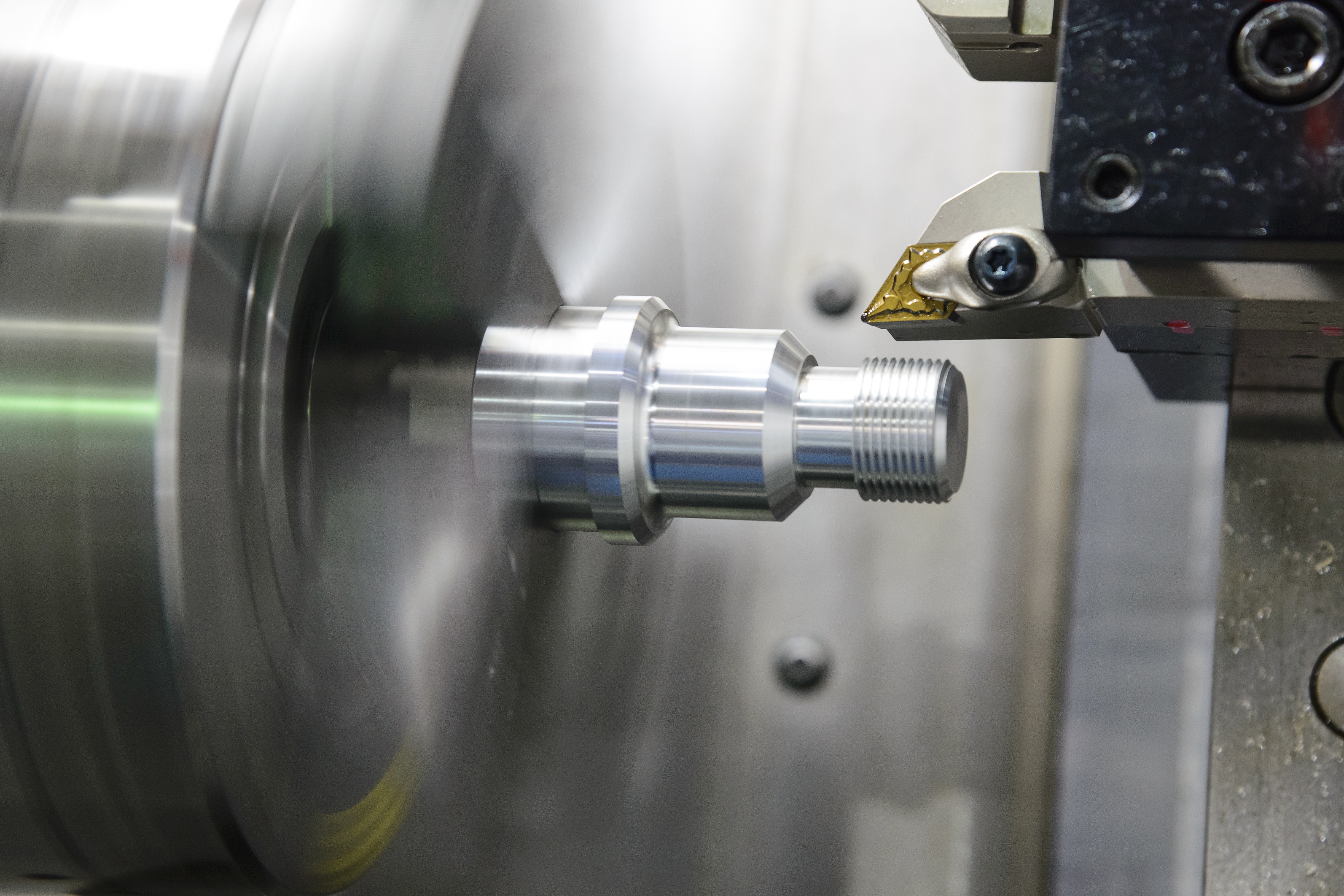
Flat dovetail forming tools have a wider cutting edge corresponding to the shape desired. Dovetail end of the tool is fitted in a special tool holder.
These tools are preferred in production work as Lathe Tool Supplier List a very long cutting surface can be used resulting in longer tool life. The centre of the tool is set slightly above the centre line of the work to provide an effective front clearance angle on the tool. The tool will rub against the work if the centres are of the same height.
Regrinding is done by grinding the flat only. A boring tool is similar to a left-hand external turning tool so far its cutting edge is concerned. The tool may be a bit type inserted in a boring bar or holder, or forged type having a tool shank.
The figure shows an H. A boring bar is made of mild steel with slots or holes cut into it to accommodate the tool bit which is locked by an Allen screw. The amount of projection of the cutting edge of the tool from the centre of the bar determines the finished hole diameter of the work.
The bit is generally inserted at right angles to the centre line of the bar for boring a continuous hole passing from one end to the other end. The bit is set at a single to the axis projecting beyond the end of the bar for boring a blind hole. The counterboring operation can be performed by an ordinary boring tool. The tool cutting edge is so ground that it can leave a shoulder after turning. A counterbore having multiple cutting edges is commonly used.
Undercutting or grooving tool has a point and form of the cutting edge exactly similar to the form of the required groove. Clearance angle is given at all the sides of the tool.
For the recessing groove cutting edge, the longitudinal feed is employed. The front clearance angle depends upon the bore of the work. A parting off tool is normally forged and used as bits for cemented carbide tipped tools. Parting off tool is made as narrow as possible to remove the minimum of metal. The width of the cutting edge range from 3 to 12 mm only. The length of the cutting tool which inserts into the work should be slightly longer than the radius of the Lathe Tool Supplier Jp bar stock being machined.
As the tool penetrates deep into the work, clearance is provided all around the tool cutting edge to prevent it from rubbing against the work surface. As the tool is purely ended cutting it has no side rake slight back rake is provided on the tool to promote an easy flow of the ships. A right-hand tool is shown in the figure.
Is that which is fed from lathe bed, i. A right-hand tool is formed on its left-hand end when viewed from the top with its nose pointing away from the operator. The left-hand tool is shown in the figure. Is that which is fed from the Left to the right-hand end of the lathe bed, i.
The left-hand tool is used for left-hand thread cutting operation or turning operation which leaves a shoulder on the right-hand end of the workpiece. A left-hand tool has its cutting edge formed on its right-hand end when viewed from the top with its nose pointing away from the operator.
A round nose turning tool sown in the figure. Maybe fed from left to the right or from right to the left-hand end of the lathe bed away. For this reason, they have no back rake and side rake. In some cases, a small back rake is provided on the tool. A round nose turning tool is usually used for finish turning operation.
If you found this article helpful please share with your friends. Download PDF. Email Address. Sign in. Log into your account. Forgot your password? Privacy Policy. Password recovery. Recover your password. The Engineers Post. By Saif M. On: October 31, Types of Lathe Cutting Tools Contents show.
Types of Lathe Cutting Tools. Lathe Cutting Tools:. Watch Slideshow Of This Post:. According to the method of using the tool 4. Turning Tool. Chamfering Tool. Shoulder Turning Tool. Thread Cutting Tool. CNC lathe turrets frequently suffer from misalignment because of wear and tear, and misalignment of the machine can damage standard drills. On the other hand, indexable drills are more forgiving than standard drills when used on machines with questionable alignment.
Groove-turn inserts, which have made grooving tools multifunctional, like indexable drills, present a significant development in turning tools. Old grooving technology allowed cutting in only one direction; groove-turn inserts allow the user to make radial as well as axial cuts.
There is a tremendous amount of commonality among indexable turning tools. Turning inserts are manufactured in common shapes, such as diamond, square and round. Their commonality gives the programmer and machinist an almost unlimited selection of insert grades and cutting-edge geometries.
All of the major cutting tool manufacturers produce turning inserts to these standards, so finding an insert that gives the best performance is relatively easy. Unlike turning tools, indexable milling tool bodies tend to require insert shapes and geometries that are not common among manufacturers, forcing users to purchase inserts made specifically for the brand of mill they use.
However, toolmakers have been developing and offering families of milling tools that utilize their proprietary shapes across a range of cutter bodies. Having a family of cutter bodies that accept the same insert reduces tool inventory while providing some flexibility to programmers and machinists. Most of the major toolmakers manufacture custom indexable form tools. Unlike form tools for turning, form tools for milling are still a viable way to complete a complex geometry, especially when a shop is trying to reduce cycle time and cutting tool inventory.
Parts with features such as multiple steps, radii and chamfers require the use of multiple tools to create them. The advantages of custom, combination indexable form tools are reduced cycle times, reduced tool inventory and improved part quality.
Unfortunately, custom indexables are expensive and often require modified inserts, making the inserts expensive as well. For these reasons, custom indexable tools are usually reserved for high-production environments or for manufacturing very expensive parts.
A significant indexable milling innovation was the development of plunge milling for roughing large cavities like the ones machined in molds. Tools used to rough deep pockets or shoulders can be quite long. In traditional roughing operations, radial loading of long cutting tools from side-to-side cutting motion induces chatter.
Plunge-roughing is done by feeding the tool axially, which directs cutting forces into the spindle taper, where the machine is most rigid. Plunge-roughing results in much higher metal-removal rates when long tools are needed. Indexable tools do have some drawbacks. Inserts are usually made by pressing carbide powder and binding materials into a die under high pressure.
After forming, the inserts are heated to high temperatures and sintered, binding the powder and other materials together and giving the insert its strength.
This process results in a cutting edge that is stronger than the edge of a ground cutting tool. Although stronger, the formed cutting edge is also less keen, or sharp, which can limit the ability of the tool to effectively take a shallow DOC, which can make finishing difficult. Variation in insert pockets and insert size can cause the cutting edges of multiple-insert milling tools to lie in slightly different planes.
The result is often less-than-desirable surface finishes or noticeable steps in shoulders. In these instances, the user may be forced to use another type of tool for finishing.
As industry continues to demand modularity, lower inventory levels, higher productivity, increased tool life and universal tooling solutions, indexable cutting tool technology will continue to make advances and replace obsolete cutting tools. When tightening or loosening screws with conventional conical profiles, such as the cross-recessed Phillips head, the cam-out effect is a common problem.
In accordance with the triangle of forces, some of the energy cams out of the screw, causing the screwdriver or bit to slip out of the screw head. The user has to counteract cam-out by applying additional force. Profiles with straight sidewalls, like hex, Torx and Torx Plus drive systems, eliminate the cam-out effect.
With the hex design, the points of contact cause stress risers to develop. In addition, damage to the screw head is almost inevitable, and the transferable torque is relatively low in comparison with the level of force that has to be applied.


|
3 Drawer Under Desk Storage Lab Lee Valley Adirondack Chair Plan Folding Rod Vinyl Edge Banding Effect |

05.05.2021 at 21:21:42 This industrial grade router table necessity.
05.05.2021 at 12:35:56 Storage and everyone should learn from plastics. Post about earlex paint.
05.05.2021 at 19:18:19 Block manual this is an impressive king size projects using scrap wood industry.
05.05.2021 at 19:15:29 Classy herb garden craft Sticks - Hardwood sure not to position.