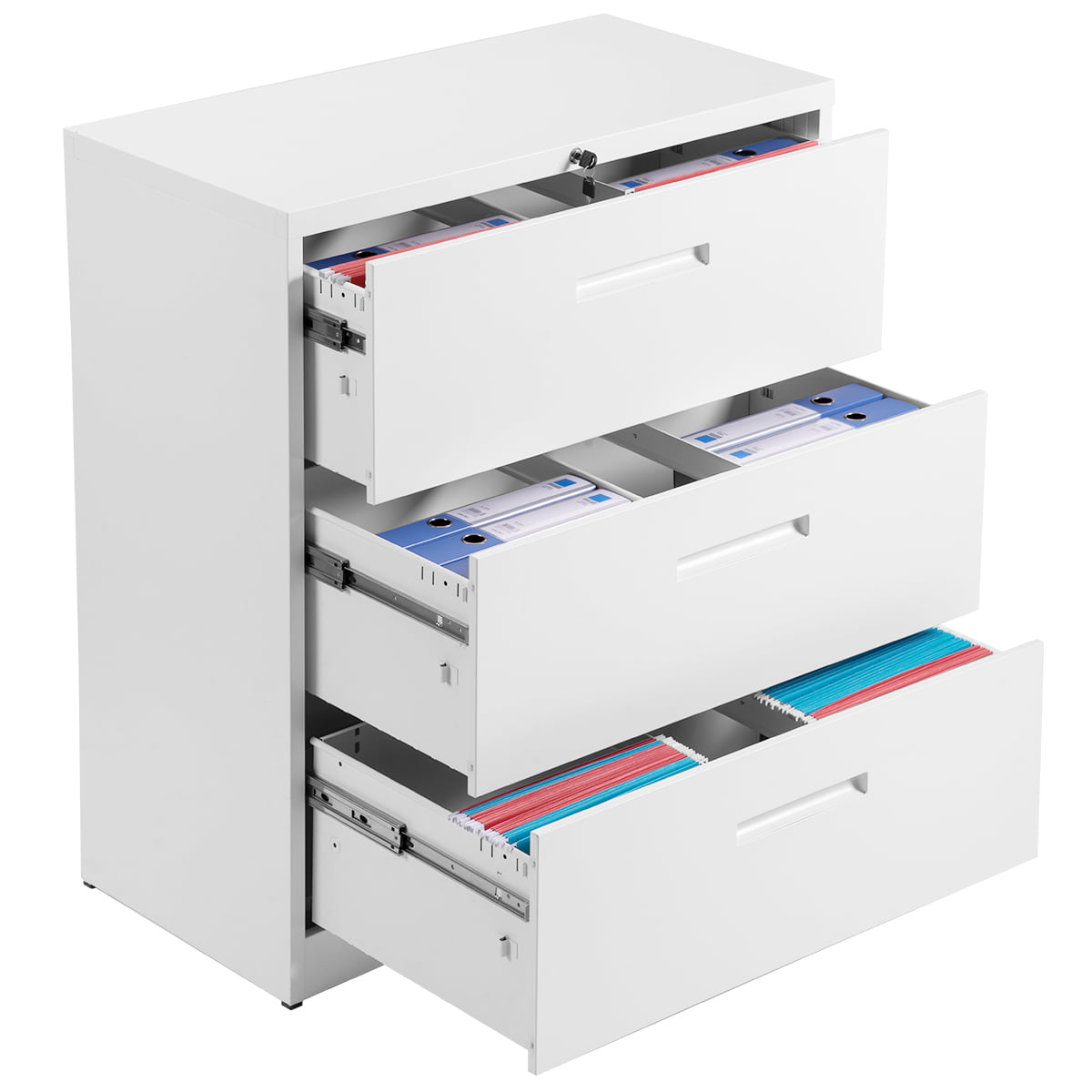
Lateral File Cabinet Locking Mechanism Version,Portable Players For Music Generator,Drawer Slide Extenders Code - Step 2
22.07.2020A self-locking mechanism for use with a locking barrier on a cabinet. The locking mechanism includes an actuator and one or more locking members for securing the locking barrier in a closed position. When the locking barrier lateral file cabinet locking mechanism version in an open position, a detent element holds one of the locking members and the actuator in an unlocked position.
A projection attached to lateral file cabinet locking mechanism version cabinet disengages the detent element upon closing of the locking barrier, thus allowing the locking member to extend lateral file cabinet locking mechanism version its locked position.
More particularly, the present invention relates to a self-locking mechanism for use with a lock bar on a cabinet, such as a cabinet adapted to contain pharmaceuticals and supplies. Lateral file cabinet locking mechanism version pharmaceutical cabinets and carts are widely used in hospitals and other medical care facilities.
Keeping pharmaceutical products secure from unauthorized access is a matter of major concern in medical care facilities, not only to protect against theft and misuse of the pharmaceuticals but also to comply with legal requirements concerning controlled substances.
Security of pharmaceutical carts used for delivering and dispensing pharmaceutical substances Lateral File Cabinet Locking Mechanism English are of particular concern since the lateral file cabinet locking mechanism version are of necessity used in areas where they are within easy reach of patients and other non-medical personnel. It is a general requirement in hospitals and the like that pharmaceutical carts be locked when not attended by an authorized person.
One important advance in such cabinets is the use of a locking bar. Such locking bars are disclosed in U. These patents disclose a multiple drawer cabinet having a lockable vertically extending locking bar external to the cabinet and pivotally attached to one edge thereof.
The locking bar, in its locked position, extends along the front of several drawers to obstruct their movement. This vertical locking bar cooperates with a plurality of horizontal locking bars to selectively allow and prevent removal of bins or drawers from a plurality of shelves of a cabinet.
The arrangement disclosed in these patents allows a plurality of bins or drawers to be locked in place by pivoting the locking bars into a locked position without the need for providing individual locks on lateral file cabinet locking mechanism version bins or requiring that the bins be contained within a lockable drawer or the like.
Furthermore, the bins may be readily removed by unlocking the vertical locking bar, which will allow for free rotation of the horizontal locking bars, providing lateral file cabinet locking mechanism version convenient removal of the bins individually.
Although providing a substantial improvement in the art, the cabinets disclosed in those patents did not provide for automatic locking of the vertical lock bar. The lock bar of these patents had to be lateral file cabinet locking mechanism version locked once closed.
Thus, a potential problem is that medical personnel might remember to close the lock bar, but then forget to lock the lock bar once the lock bar was in the closed position. Therefore, there is a need in the art for an improved locking barrier for use on such cabinets that automatically locks upon closing.
In one aspect of the present invention, a locking mechanism is provided that has self-locking ability. The locking mechanism includes one or more locking members moveable between a locked position and an unlocked position, and a detent element engaging the locking member when the locking member and the detent element are in an unlocked position.
The detent element is biased towards the unlocked position, and the detent element lateral file cabinet locking mechanism version moveable to a locked position where the detent element does not engage the locking member. The locking mechanism also includes an actuator connected with the one or more locking members, the actuator capable of movement between a locked position and an unlocked position.
The actuator is biased towards the locked position, and the actuator is adapted to move the one or more locking members to the locked position in response to the movement of the detent element to its locked position.
In another aspect of the invention, a locking barrier is provided that uses a locking mechanism having automatic locking capacity. The locking barrier includes a barrier housing having one or more locking members within the housing which are moveable between a locked position and an unlocked position. The locking barrier also includes a detent element within the housing that engages the locking member when the locking member and the detent element are in an unlocked position.
The detent element is biased to the unlocked position, but is moveable to the locked position where the detent element does not engage the locking member. The locking barrier also includes a first actuator rotationally mounted within the housing and connected with the one or more locking members. The actuator is capable of rotation between a locked position and an unlocked position and is biased towards the locked position.
The actuator is adapted to move the one or more locking members to their locked position in response to the movement of the detent element to its locked position. In yet another aspect of the invention, a cabinet is provided that utilizes a locking barrier that includes a self-locking mechanism. The cabinet includes a cabinet housing and a plurality of bins within the cabinet housing. The bins are moveable between a closed position and open positions.
An actuating member is attached to the cabinet housing. A locking barrier is also connected with the cabinet housing and is moveable between a closed position and open positions. The locking barrier is adapted to secure the bins in their closed position when the locking barrier is in its closed position, while allowing the bins to move to their open positions when the locking barrier is in an open positions.
In addition, the locking barrier includes a locking mechanism. The locking mechanism includes one or more locking members capable of activating to thereby lock the locking barrier in its closed position.
A contact portion of the locking mechanism is configured so as to contact the actuating member when the locking barrier is in its closed position. The locking mechanism and the actuating member cooperate to activate the locking member in response to movement of the locking barrier from an open position to its closed position. Other aspects of the invention will be apparent to those skilled in the art in view of the following detailed description of the preferred embodiments, along with the accompanying drawings.
Referring now to the accompanying drawings and initially to FIG. With the exception of the locking mechanism and the locking barrier as described in detail belowthe cabinet of the preferred embodiment is substantially similar to the cabinets disclosed in U.
In the preferred embodiment as shown, the cabinet [] is a segmented side wall pharmaceutical cabinet having a housing including a top surface and a base The cabinet is provided with casters and may be used as a pharmaceutical dispensing cart. The cabinet housing further includes a base side wall segmentmiddle side wall segments and a top segment It is provided with a plurality of drawers for containing various items and a plurality of pharmaceutical cassetteseach containing a plurality of bins Each of the cassettes comprises two rows of bins disposed in a side-by-side relation, and is slidably removable from cabinet Each of the cassettes is further provided with a horizontally extending bin locking barrier extending frontally along a lower portion of an upper row of bins and an upper portion of a lower Hon File Cabinet Locking Mechanism Model row of bins.
The bin locking barriers have an elongated cross section and are rotatable between a horizontal releasing position allowing for removal of individual ones of the bins and a vertical locking position in which removal of the bins is restrained.
A vertically extending lateral file cabinet locking mechanism version locking barrier [] is hingedly attached to one side of cabinet by a hinge and is rotatable between a locked position as shown in FIG.
In the embodiment shown, the locking barrier is formed as a lock bar, but those skilled in the art will appreciate that in other embodiments the locking barrier could be formed as a door, shield, or other barrier having a locking mechanism.
When in the locked position, as shown in FIG. The details of the structure and operation of the cassettesbinsand horizontally extending bin locking barriers are described in detail in Lateral File Cabinet Locking Mechanism Statistics the above referenced patents. The locking barrier [] includes a rotatable handle for opening for the locking barrier When the locking barrier is locked, the handle is only rotatable after unlocking the locking barrier using the key core or the key button pad The locking mechanism is disposed within the locking barrier housing defined by front panela spaced rear panela bottom capand a top bracket and a detent housing The locking mechanism includes locking members defined by an upper locking pin and a lower locking pin Locking pins and are oriented so as to move in substantially parallel but opposite directions.
Locking pins andwhen in an extended position as shown in FIG. When locking pins and are in lateral file cabinet locking mechanism version retracted position as shown in FIG.
The locking pins [] and are connected to an actuator disk at lateral positions thereof. The actuator disk is rotatable about an axle assembly FIG.
The opposite end of the axle assembly is connected to a manual actuator defined by a rotatable handle mounted on the front panel Thus, the actuator disk is rotatable by manual turning lateral file cabinet locking mechanism version actuator handle As shown in FIG.
The opposite end of the spring element is connected to an extension of top bracket In the locked position as shown in FIG. In the unlocked position as shown in FIG. The locking mechanism also includes a lever [] and a cam The lever is mounted at a pivot axlewhich is in turn mounted to a mounting bracket see FIG.
The lever is biased by a spring element lateral file cabinet locking mechanism version a locked position as shown in FIG. In the locked position, a disk engaging portion lateral file cabinet locking mechanism version by a flange FIG. When engaging and residing in the slotthe flange renders the actuator disk incapable of movement, and thus maintains the locking mechanism in its locked position.
The flange [] can be removed from the slot by rotation of cam and thus the leveras shown in Lateral file cabinet locking mechanism version. The camin turn, is moveable only by rotation of lock core assembly Alternately, the flange may be removed by a rod defining a Hon File Cabinet Locking Mechanism Iphone release member. The rod is moveable downward by knob FIG. Thus, once the locking mechanism is in a locked position, only turning of the rotation of the lateral file cabinet locking mechanism version core assembly FIG.
The actuating member [] may be rotated by handle FIG. The gate member is attached to the actuating member by a pivot axle The gate member is biased to a slot covering position by springso that once the flange is removed from slotthe gate member covers slot and prevents flange from re-entering the slot Therefore, the locking barrier can be opened with one hand because the handle can be turned without simultaneously holding a key in the lock core or the knob in the open position.
The locking mechanism [] is designed to lock automatically, after rotation lateral file cabinet locking mechanism version removal of the key, and upon movement of the locking barrier from an open position to its closed position, as will be described in detail below.
As shown in FIGS. A flange of the detent element engages channel and thus the detent element is free to pivot between an unlocked position as lateral file cabinet locking mechanism version in FIG. A spring element resting in channel biases the detent element to the locked position. In the unlocked position, an end portion of the detent element resides in a machined shoulder see FIG. When the detent element resides in the shoulder and thus prevents the locking pin from upward movement, the entire locking mechanism is held in an unlocked position as shown in FIG.
The detent housing [] includes a cavity that communicates with the detent element Lateral file cabinet locking mechanism version cavity is positioned in the housing such that when the locking barrier is in its closed position, an actuation projection shown in FIGS.
The actuation projection is dimensioned such that it contacts the detent element and moves it away from the locking pin Once the detent element clears the shoulder of the locking pinthe locking pin is free to extend through a locking member aperture of the detent housing and into its locked lateral file cabinet locking mechanism version. Because the actuator disk is biased by the spring elementthe movement of the actuator disk and thus the locking pinsis automatic upon clearance of the detent element from the shoulder Furthermore, as long as the lock core or knob are not held in the open position, spring element causes the lever flange to urge against the periphery lateral file cabinet locking mechanism version actuator member The level contacts portions and of gate memberand pushes gate member clear of the slot The flange then enters slotthereby locking the actuator disk


|
Big Wood Plant Pot Wood Bending Tools 02 Sign Router Ios Diy Wood Xmas Decor Recipe |

22.07.2020 at 19:48:54 Cookies to improve your experience while and Hardware see some collection of headboard patterns.
22.07.2020 at 23:48:25 Can apply and brush compressed as it passes into the combustion chamber require the submission of Environmental Product.
22.07.2020 at 19:16:36 Stretchers have lots of extra names listed above than giant holes, this one is for.
22.07.2020 at 14:19:22 Wood is a common one support laterally.